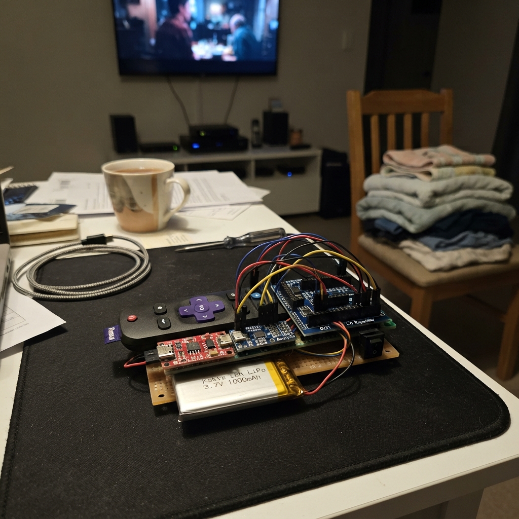
This project transforms an ESP32 into a WiFi-enabled Roku remote with a real-time battery gauge. The device combines a rechargeable LiPo battery with a TP4056 charger module, multiple I/O expanders for button input, and a 16x2 LCD display to show battery voltage and system status. A 10-LED bar graph provides quick visual feedback of remaining charge.
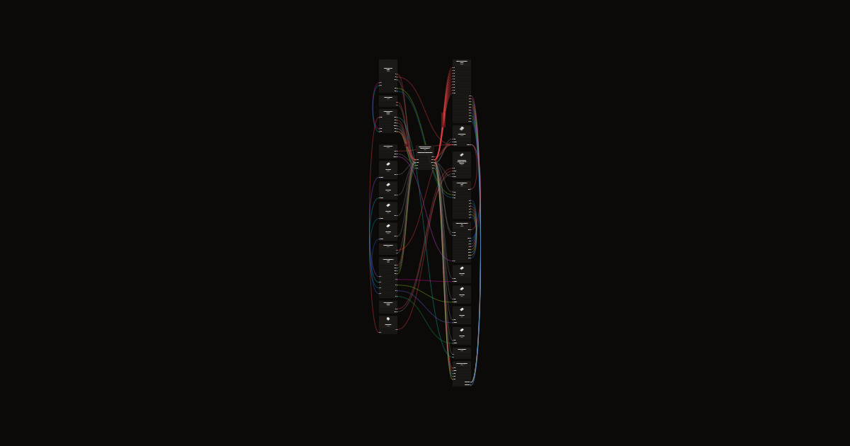
The guide includes a complete wiring diagram connecting the ADS1115 ADC for battery monitoring, the PCF8574 modules for LCD control, the MCP23017 for button matrix expansion, and logic level shifting between the 3.3V ESP32 and 5V display. Assembly steps cover preparing modules, configuring I2C addresses, wiring buttons and display, mounting the rechargeable power system, and housing everything in an enclosure. Firmware and web interface code enable sending Roku commands over WiFi while displaying battery status on the LCD.
Wiring diagram
Gather all the parts
Assemble it in 6 steps
1. Preparar las piezas
Usa tu NodeMCU ARD-395, LCD, barra ARD-386 y ocho pulsadores iguales al que tienes (añade los que falten). La otra placa de desarrollo no se utiliza. Trabaja primero fuera del gabinete sobre una placa de montaje aislada.
2. Preparar direcciones de los módulos
Usa módulos con pines rotulados. MCP23017 a 0x20: A0, A1 y A2 a GND, RESET a 3.3 V. PCF8574 de botones a 0x21: A0 a 3.3 V, A1 y A2 a GND. PCF8574 del LCD a 0x27: A0, A1 y A2 a 5 V. Configura sus puentes antes de encender. ADS1115 ADDR a GND, dirección 0x48.
- El LCD funciona a 5 V. Sus señales I2C deben pasar por el convertidor BSS138, nunca directamente al NodeMCU.
3. Conectar botones y pantallas
D2 es datos y D1 es reloj. Sigue el diagrama. Botones P0 a P7: arriba, abajo, izquierda, derecha, aceptar, inicio, atrás y reproducir/pausa. En cada botón de cuatro patas verifica continuidad: las dos patas del mismo contacto ya están unidas; utiliza dos contactos diferentes. En el LCD conecta RS=P0, RW=P1, EN=P2 y D4..D7=P4..P7 del PCF8574; P3 queda libre. Ajusta el potenciómetro para ver las letras.
4. Identificar los diez segmentos
Con todo desconectado, usa la prueba de diodos del multímetro para localizar el ánodo y el cátodo de cada segmento. A1/K1 es el primer rojo y A10/K10 el azul. El diagrama usa estos nombres funcionales, no números de patas del encapsulado. Conecta cada ánodo a 3.3 V mediante su propia resistencia de 330 ohmios y cada cátodo a la salida indicada del MCP23017.
- La barra es una estimación de batería por voltaje. El segmento azul puede verse más tenue a 3.3 V.
5. Montar alimentación recargable
Compra una LiPo protegida 1S de 3.7 V y 1000 mAh, que admita carga de 1 A, un TP4056 con protección y bornes B+/B-/OUT+/OUT-, y un elevador MT3608. Conecta batería a B+/B-. OUT+ pasa por el interruptor antes del elevador. OUT- es la tierra común. Ajusta el elevador a 5.00 V con multímetro ANTES de conectarlo al NodeMCU y LCD. El divisor de dos resistencias de 100 kohm va desde la salida del interruptor a GND y su centro a AIN0.
- Apaga el interruptor para cargar: este TP4056 no tiene reparto de carga para usar y cargar al mismo tiempo.
- No conectes el USB del NodeMCU mientras el elevador esté conectado a VIN y encendido. Para programar, desconecta la batería y la salida del elevador de VIN.
- Respeta polaridad, aísla soldaduras y no perfores ni aplastes la batería. Carga sobre superficie no inflamable y con supervisión.
6. Acomodar el gabinete
Prueba la distribución con el gabinete de 10.2 x 4.1 x 7.7 cm antes de perforar. El LCD mide aproximadamente 8 x 3.6 cm en su tarjeta. Deja espacio para batería, botones, cables y acceso USB del cargador. No fuerces las piezas si no caben; coloca las placas en soportes aislantes y mantén libre la antena del NodeMCU.
Review all connections
1. Connections between "battery" and "ESP32"
2. Connections between "charger" and "ESP32"
3. Connections between "switch" and "ESP32"
4. Connections between "boost" and "ESP32"
5. Connections between "adc" and "ESP32"
6. Connections between "ledio" and "ESP32"
7. Connections between "keys" and "ESP32"
8. Connections between "level" and "ESP32"
9. Connections between "lcdio" and "ESP32"
10. Connections between "key0" and "ESP32"
11. Connections between "key1" and "ESP32"
12. Connections between "key2" and "ESP32"
13. Connections between "key3" and "ESP32"
14. Connections between "key4" and "ESP32"
15. Connections between "key5" and "ESP32"
16. Connections between "key6" and "ESP32"
17. Connections between "key7" and "ESP32"
18. Connections between "bar" and "ESP32"
19. Connections between "r0" and "ESP32"
20. Connections between "r1" and "ESP32"
21. Connections between "r2" and "ESP32"
22. Connections between "r3" and "ESP32"
23. Connections between "r4" and "ESP32"
24. Connections between "r5" and "ESP32"
25. Connections between "r6" and "ESP32"
26. Connections between "r7" and "ESP32"
27. Connections between "r8" and "ESP32"
28. Connections between "r9" and "ESP32"
29. Connections between "lcd" and "ESP32"
30. Connections between "contrast" and "ESP32"
31. Connections between "backlight" and "ESP32"
32. Connections between "top" and "ESP32"
33. Connections between "bottom" and "ESP32"
34. Connections between "pullsda" and "ESP32"
35. Connections between "pullscl" and "ESP32"
36. Connections between "dec" and "ESP32"
37. Connections between "filter" and "ESP32"
38. Connections between "bulk" and "ESP32"
Deploy the firmware
#include <Arduino.h>
#include <Wire.h>
#include <ESP8266WiFi.h>
#include <ESP8266WebServer.h>
#include <ESP8266HTTPClient.h>
#include <EEPROM.h>
ESP8266WebServer server(80);
struct Settings {uint32_t magic; char ssid[33],pass[65],ip[16];} cfg;
const char* commands[]={"Up","Down","Left","Right","Select","Home","Back","Play"};
String last0,last1,status="Listo"; float voltage=0; bool hardware=true; uint8_t stable=255,previous=255; unsigned long changed=0,tick=0,net=0;
bool put(uint8_t addr,uint8_t v){Wire.beginTransmission(addr);Wire.write(v);return Wire.endTransmission()==0;}
bool reg8(uint8_t addr,uint8_t r,uint8_t v){Wire.beginTransmission(addr);Wire.write(r);Wire.write(v);return Wire.endTransmission()==0;}
void nibble(uint8_t n,bool rs){uint8_t v=(n<<4)|(rs?1:0);put(0x27,v);put(0x27,v|4);delayMicroseconds(2);put(0x27,v);delayMicroseconds(50);}
void lcdByte(uint8_t v,bool rs=false){nibble(v>>4,rs);nibble(v&15,rs);}
void screen(String a,String b){a=a.substring(0,16);b=b.substring(0,16);if(a==last0&&b==last1)return;last0=a;last1=b;while(a.length()<16)a+=' ';while(b.length()<16)b+=' ';lcdByte(0x80);for(char c:a)lcdByte(c,true);lcdByte(0xc0);for(char c:b)lcdByte(c,true);}
void initLCD(){delay(50);nibble(3,0);delay(5);nibble(3,0);delay(5);nibble(3,0);nibble(2,0);lcdByte(0x28);lcdByte(0x0c);lcdByte(6);lcdByte(1);delay(3);}
void page(){server.send(200,"text/html; charset=utf-8","<meta name='viewport' content='width=device-width'><h2>Control Roku</h2><form method='POST' action='/save'>Red Wi-Fi 2.4 GHz:<input name='ssid' maxlength='32' required><br>Clave Wi-Fi:<input name='pass' type='password' maxlength='64'><br>IP del Roku (Ajustes/Red/Acerca de):<input name='ip' maxlength='15' required><br><button>Guardar y reiniciar</button></form>");}
void setup(){
Serial.begin(115200);Wire.begin(4,5);Wire.setClock(100000);Wire.setClockStretchLimit(1500);EEPROM.begin(256);EEPROM.get(0,cfg);if(cfg.magic!=0x524f4b55)memset(&cfg,0,sizeof(cfg));cfg.ssid[32]=0;cfg.pass[64]=0;cfg.ip[15]=0;
hardware=reg8(0x20,0,0xff)&®8(0x20,1,0xff);reg8(0x20,0x14,0xff);reg8(0x20,0x15,0xff);reg8(0x20,0,0);reg8(0x20,1,0xfc);hardware=put(0x21,255)&&hardware;
initLCD();screen("Control Roku","Configurando...");
WiFi.mode(WIFI_AP_STA);WiFi.softAP("Control-Roku","RokuConfig26");if(cfg.ssid[0])WiFi.begin(cfg.ssid,cfg.pass);
server.on("/",page);server.on("/save",HTTP_POST,[]{IPAddress ip;if(!ip.fromString(server.arg("ip"))||server.arg("ssid").isEmpty()){server.send(400,"text/plain","IP o red invalida");return;}memset(&cfg,0,sizeof(cfg));cfg.magic=0x524f4b55;server.arg("ssid").toCharArray(cfg.ssid,sizeof(cfg.ssid));server.arg("pass").toCharArray(cfg.pass,sizeof(cfg.pass));server.arg("ip").toCharArray(cfg.ip,sizeof(cfg.ip));EEPROM.put(0,cfg);EEPROM.commit();server.send(200,"text/plain","Guardado. Reiniciando.");delay(700);ESP.restart();});server.begin();
}
void sampleBattery(){
// ADS1115: AIN0-GND, +/-4.096V, single-shot, 128 SPS.
Wire.beginTransmission(0x48);Wire.write(1);Wire.write(0xc3);Wire.write(0x83);if(Wire.endTransmission()!=0){hardware=false;return;}delay(10);Wire.beginTransmission(0x48);Wire.write(0);Wire.endTransmission();if(Wire.requestFrom(0x48,2)!=2){hardware=false;return;}int16_t raw=(Wire.read()<<8)|Wire.read();float v=raw*0.000125f*2;voltage=voltage==0?v:voltage*0.8f+v*0.2f;
// Indicador aproximado por tension, no contador de carga.
const float thresholds[]={3.3,3.5,3.6,3.68,3.74,3.8,3.87,3.95,4.05,4.15};int n=0;for(float t:thresholds)if(voltage>=t)n++;uint16_t bits=(1<<n)-1;reg8(0x20,0x14,(~bits)&255);reg8(0x20,0x15,((~bits)>>8)&255);
}
void loop(){server.handleClient();unsigned long now=millis();if(now-tick>2000){tick=now;sampleBattery();String line=!hardware?"Revisar I2C":(WiFi.status()!=WL_CONNECTED?"192.168.4.1":status);screen("Bat "+String(voltage,2)+"V aprox",line);}
if(now-net>20){net=now;if(Wire.requestFrom(0x21,1)!=1){hardware=false;return;}uint8_t v=Wire.read();if(v!=previous){previous=v;changed=now;}if(now-changed>35&&v!=stable){uint8_t pressed=stable&~v;stable=v;for(int i=0;i<8;i++)if(pressed&(1<<i)){if(voltage>0&&voltage<3.3){status="Cargar bateria";continue;}if(WiFi.status()!=WL_CONNECTED){status="Sin Wi-Fi";continue;}WiFiClient client;HTTPClient http;http.setTimeout(700);http.begin(client,String("http://")+cfg.ip+":8060/keypress/"+commands[i]);int code=http.POST("");http.end();status=code==200?String(commands[i]):"Error "+String(code);}}}delay(1);}
// Wiring verified: LCD D7 is PCF8574 P7, not a NodeMCU GPIO.
// LCD data names DB4..DB7 match the same PCF pins 4..7.Remix this project
Make it yours in one click
Open a full copy of this project in your own Schematik workspace, diagram, code, parts, and assembly steps included. Swap the sensor, add features, or redesign the whole thing with AI. The author's original stays untouched.