Community project
Schematik Project Blueprint Smart Power Pedestal
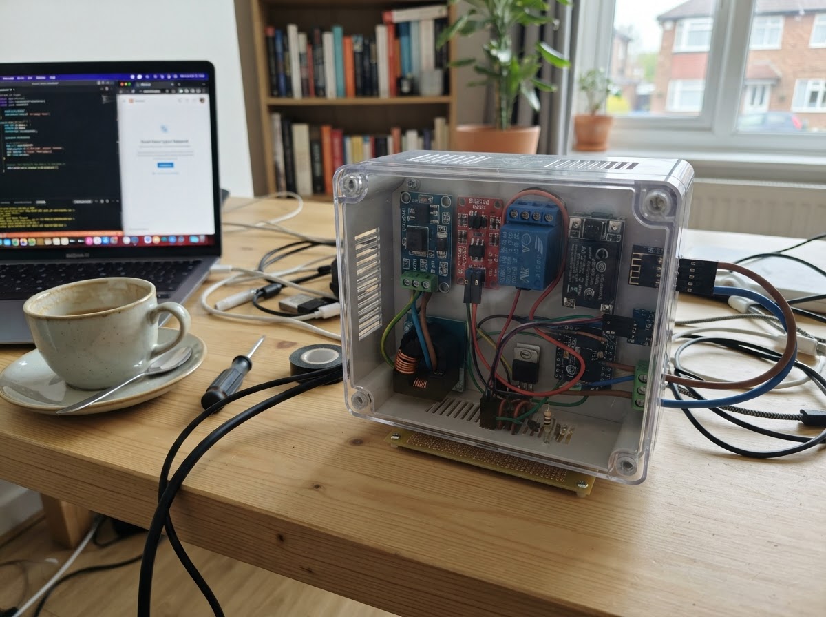
This project builds a smart power pedestal controller using an ESP32 microcontroller and a 30 A latching relay to remotely switch power on and off. The dual-coil relay design requires minimal holding current, making it ideal for battery-powered or always-on monitoring applications. The system includes a watchdog timer that automatically cuts power if the ESP32 stops sending heartbeat signals, providing a safety mechanism for unattended equipment.
The guide provides a complete wiring diagram, parts list, and step-by-step assembly instructions starting with low-voltage testing before any AC power connections. Builders will receive the full firmware code for relay control via serial commands, including the UNLOCK, LOCK, and HEARTBEAT logic that manages the power state and safety timeout. The modular design allows the relay driver to be adapted for various desk-based power distribution or remote shutdown applications.
Wiring diagram

Gather all the parts
Assemble it in 7 steps
1. Keep the first test away from AC power
For this desk test, leave the relay contact terminals marked COM and NO completely unused. Do not connect the PZEM, an outlet, a boat, or any 120/240 V wiring. You are only testing the 5 V relay coils and the safety timer.
- Put a small label over the relay contact terminals so they cannot be mistaken for the coil terminals.
- Connecting mains power during this first test can cause electric shock, fire, or damage; the contacts are not part of the desk-demo wiring.
2. Make a common low-voltage ground
Connect the negative or GND output of the 5 V USB bench supply to a GND pin on the T3-S3. This shared ground gives the two MOSFET drivers the same electrical reference as GPIO10 and GPIO21.
- Use black wire for every ground connection to make the circuit easier to inspect.
- Without the shared ground, the relay drivers may not turn on even if their indicator LEDs light.
3. Wire the SET coil driver
Connect relay SET+ to the bench supply +5 V. Connect relay SET- to the Drain (D) of mosfet_set_1. Connect its Source (S) to GND. Connect GPIO10 through gate_resistor_set_1 (100 Ω) to its Gate (G), then connect gate_pulldown_set_1 (10 kΩ) from that same gate point to GND.
- On the AO3400A SOT-23 package, verify the pin positions from the seller’s datasheet before soldering; the package is very small.
- Do not swap the MOSFET Drain and Source; the coil may fail to switch or behave unpredictably.
4. Add the green SET pulse light and diode
Connect the long leg of the green set_pulse_led_1 to set_indicator_resistor_1 (1 kΩ), then connect the other resistor end to the SET MOSFET Gate (G). Connect the LED short leg to GND. Put flyback_set_1 directly across the SET coil: its striped cathode end goes to SET+ and its unstriped anode end goes to SET-.
- The green LED should flash only during a SET pulse. The stripe on the diode is the cathode mark.
- A reversed flyback diode makes a direct short across the 5 V supply when the coil is pulsed.
5. Wire the RESET coil driver
Connect relay RESET+ to the bench supply +5 V. Connect relay RESET- to the Drain (D) of mosfet_reset_1. Connect its Source (S) to GND. Connect GPIO21 through gate_resistor_reset_1 (100 Ω) to its Gate (G), then connect gate_pulldown_reset_1 (10 kΩ) from that gate point to GND.
- Use a different wire color for the RESET coil route so it cannot be mixed up with the SET coil.
- Do not join SET- and RESET- together; each coil needs its own MOSFET driver.
6. Add the red RESET pulse light and diode
Connect the long leg of reset_pulse_led_1 to reset_indicator_resistor_1 (1 kΩ), then connect the other resistor end to the RESET MOSFET Gate (G). Connect its short leg to GND. Put flyback_reset_1 across the RESET coil: striped cathode to RESET+ and unstriped anode to RESET-.
- The red LED flashes at startup and when you send LOCK or let the watchdog expire.
- Make sure the LED long and short legs are not swapped — a reversed LED will not show the pulse.
7. Power and test the desk prototype
Power the T3-S3 from its USB-C port and power the relay coils from the separate regulated 5 V bench supply. Open Schematik’s serial console after Deploy and send UNLOCK followed by Enter. The green LED should flash once. Send HEARTBEAT every 10–20 seconds to keep it enabled, send LOCK to flash the red LED, or stop heartbeats and wait 60 seconds for the red watchdog pulse.
- Send STATUS at any time to see whether the firmware believes the relay is enabled.
- Do not use an unregulated supply or a supply above 5 V for the relay coils; excessive coil voltage can damage the relay.
Review all connections
1. Connections between "relay_1" and "ESP32"
2. Connections between "gate_pulldown_set_1" and "ESP32"
3. Connections between "gate_pulldown_reset_1" and "ESP32"
4. Connections between "flyback_set_1" and "ESP32"
5. Connections between "flyback_reset_1" and "ESP32"
6. Connections between "mosfet_set_1" and "ESP32"
7. Connections between "mosfet_reset_1" and "ESP32"
8. Connections between "gate_resistor_set_1" and "ESP32"
9. Connections between "gate_resistor_reset_1" and "ESP32"
10. Connections between "set_indicator_resistor_1" and "ESP32"
11. Connections between "set_pulse_led_1" and "ESP32"
12. Connections between "reset_indicator_resistor_1" and "ESP32"
13. Connections between "reset_pulse_led_1" and "ESP32"
14. Connections between "bench_5v_usb_supply_1" and "ESP32"
Deploy the firmware
#include <Arduino.h>

// LILYGO T3-S3 desk prototype: low-voltage relay-driver and watchdog test.
// GPIO10 closes (SET) a 5 V latching-relay coil through its MOSFET driver.
// GPIO21 opens (RESET) the other coil through its MOSFET driver.

// Forward declarations
void pulsePin(uint8_t pin, const char *label);
void openRelay();
void closeRelay();
void handleCommand(String command);

constexpr uint8_t RELAY_SET_PIN = 10;
constexpr uint8_t RELAY_RESET_PIN = 21;
constexpr unsigned long PULSE_DURATION_MS = 100;
constexpr unsigned long HEARTBEAT_TIMEOUT_MS = 60000;

bool powerEnabled = false;
unsigned long lastHeartbeatMs = 0;

void pulsePin(uint8_t pin, const char *label) {
  Serial.printf("[RELAY] %s pulse for %lu ms\n", label, PULSE_DURATION_MS);
  digitalWrite(pin, HIGH);
  delay(PULSE_DURATION_MS);
  digitalWrite(pin, LOW);
}

void openRelay() {
  if (powerEnabled) {
    pulsePin(RELAY_RESET_PIN, "OPEN / RESET");
    powerEnabled = false;
  }
}

void closeRelay() {
  if (!powerEnabled) {
    pulsePin(RELAY_SET_PIN, "CLOSE / SET");
    powerEnabled = true;
  }
}

void handleCommand(String command) {
  command.trim();
  command.toUpperCase();

  if (command == "HEARTBEAT") {
    lastHeartbeatMs = millis();
    Serial.println("[WATCHDOG] Heartbeat accepted.");
  } else if (command == "UNLOCK") {
    lastHeartbeatMs = millis();
    closeRelay();
    Serial.println("[STATE] Power enabled; send HEARTBEAT within 60 seconds.");
  } else if (command == "LOCK") {
    openRelay();
    Serial.println("[STATE] Power disabled.");
  } else if (command == "STATUS") {
    const unsigned long age = millis() - lastHeartbeatMs;
    Serial.printf("[STATUS] power=%s, heartbeat_age_ms=%lu\n", powerEnabled ? "ON" : "OFF", age);
  } else if (command.length() > 0) {
    Serial.println("[HELP] Commands: UNLOCK, LOCK, HEARTBEAT, STATUS");
  }
}

void setup() {
  pinMode(RELAY_SET_PIN, OUTPUT);
  pinMode(RELAY_RESET_PIN, OUTPUT);
  digitalWrite(RELAY_SET_PIN, LOW);
  digitalWrite(RELAY_RESET_PIN, LOW);

  Serial.begin(115200);
  const unsigned long serialWaitStarted = millis();
  while (!Serial && (millis() - serialWaitStarted < 1500)) {
    delay(10);
  }

  // Deliberately pulse RESET once at startup: the desk prototype begins open.
  pulsePin(RELAY_RESET_PIN, "STARTUP OPEN / RESET");
  powerEnabled = false;
  lastHeartbeatMs = millis();
  Serial.println("[SYSTEM] T3-S3 relay watchdog desk test ready.");
  Serial.println("[HELP] Commands: UNLOCK, LOCK, HEARTBEAT, STATUS");
}

void loop() {
  if (Serial.available() > 0) {
    handleCommand(Serial.readStringUntil('\n'));
  }

  if (powerEnabled && (millis() - lastHeartbeatMs >= HEARTBEAT_TIMEOUT_MS)) {
    Serial.println("[SAFETY] Heartbeat timed out; opening relay.");
    openRelay();
    lastHeartbeatMs = millis();
  }
}
Remix this project
Make it yours in one click
Open a full copy of this project in your own Schematik workspace — diagram, code, parts, and assembly steps included. Swap the sensor, add features, or redesign the whole thing with AI. The author's original stays untouched.