Community project
Smart Classroom Safety System
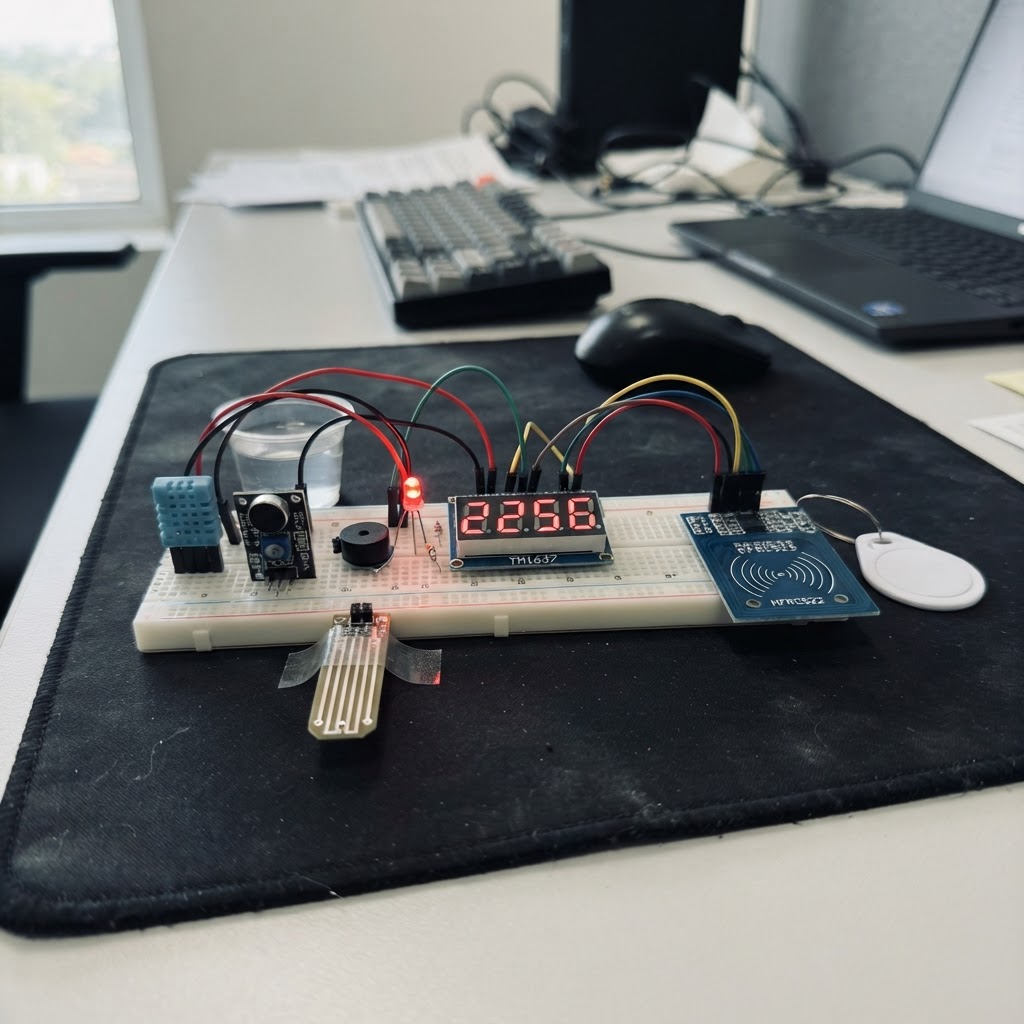
This smart classroom safety system monitors environmental conditions and detects potential hazards using an Arduino Uno and a suite of sensors. It tracks temperature and humidity with the DHT11, detects sound levels with the KY-038 microphone, monitors water presence, measures motion with the MPU-6050 accelerometer, and uses RFID cards for attendance tracking. Visual and audio alerts via LEDs and a buzzer respond to unsafe conditions, while a 4-digit display shows real-time data and class duration countdown.
This guide provides a complete wiring diagram, parts list, and step-by-step assembly instructions for connecting all sensors to the Arduino breadboard. You'll also get the full firmware code that implements environmental monitoring, motion detection for seismic events, noise level tracking, water leak detection, and RFID-based access control—everything needed to deploy a functional safety monitoring system in an educational setting.
Wiring diagram

Gather all the parts
Assemble it in 12 steps
1. Set up your breadboard and power rails
Place your 830-point breadboard on the desk. Connect the Arduino's 5V pin to the breadboard's + power rail and GND to the − rail using jumper wires. Also run a short wire from the Arduino's 3.3V pin to a separate row you'll use for the RFID module.
- Use red wire for power (+) and black wire for ground (−) to keep things organised.
2. Wire the DHT11 temperature & humidity sensor
Place the DHT11 on the breadboard. Connect VCC → 5V rail, GND → GND rail, DATA → Arduino D7. Add a 10 kΩ pull-up resistor between DATA and VCC (included in the kit).
- The flat face of the DHT11 faces you. Pin order left-to-right: VCC, DATA, NC, GND.
3. Wire the Green Fan/Heat LED
Place the green LED on the breadboard. Connect the ANODE (long leg) through a 220 Ω resistor to Arduino D6. Connect the CATHODE (short leg) to the GND rail. This LED lights up when the classroom is too hot.
- Always use the 220 Ω resistor in series — never connect an LED directly to a GPIO.
4. Wire the Red Do Not Disturb LED
Place the red LED on the breadboard. Connect the ANODE (long leg) through a 220 Ω resistor to Arduino D4. Connect the CATHODE (short leg) to the GND rail. This LED lights up when the teacher enables Do Not Disturb by scanning their RFID card.
- Always use the 220 Ω resistor in series.
5. Wire the Buzzer
Place the active buzzer on the breadboard. Connect SIGNAL (+ pin, usually marked) → Arduino D5. Connect GND → GND rail. The buzzer sounds for flood alerts, earthquake alerts, and class dismissal.
- The active buzzer has a built-in oscillator — it beeps with just HIGH/LOW; no tone() needed.
6. Wire the KY-038 Sound Sensor
Place the KY-038 on the breadboard. Connect VCC → 5V rail, GND → GND rail, DO (digital output) → Arduino A3 (used as digital pin 17). Turn the small blue potentiometer on the module to set the noise trigger level — clockwise = more sensitive.
- Use the DO pin only. The AO (analog out) pin is left unconnected for this project.
7. Wire the Water Level Sensor
Place the water level sensor module near the edge of the breadboard. Connect + → Arduino D12 (pulsed power), − → GND rail, S (signal) → Arduino A0. The sensor is powered only when reading to reduce electrode corrosion.
- Keep the sensor probe flat and at the depth you want to detect flooding.
- Do not leave the sensor powered continuously — it corrodes. The firmware handles pulsed power automatically.
8. Wire the TM1637 4-Digit 7-Segment Display
Place the TM1637 module on the breadboard. Connect VCC → 5V rail, GND → GND rail, CLK → Arduino D8, DIO → Arduino D9. This display shows the 45-minute class countdown in MM:SS format.
- The TM1637 module only needs 4 wires total — very simple to connect.
9. Wire the MFRC522 RFID Module
Place the RFID module on the breadboard. Connect: VCC → 3.3V rail (important!), GND → GND rail, SCK → D13, MOSI → D11, MISO → D12, SDA (SS) → D10, RST → D11. Use the shorter jumper wires for the SPI lines to keep connections neat.
- The blue Elegoo MFRC522 breakout tolerates 5V SPI signal lines — only the VCC pin needs 3.3V.
- The RFID module MUST be powered from 3.3V, NOT 5V — using 5V will damage it permanently.
- Double-check every SPI connection before powering on.
10. Wire the MPU-6050 Gyroscope/Accelerometer
Place the MPU-6050 module on the breadboard. Connect VIN → 5V rail, GND → GND rail, SDA → Arduino A4, SCL → Arduino A5. The MPU-6050 shares the I2C bus — if you have the DHT11 pull-up resistors already in place, no extra pull-ups are needed.
- Mount the MPU-6050 flat and level on the desk — it detects sharp vibrations as earthquake events.
- A4 and A5 on the UNO are the dedicated hardware I2C pins.
11. Connect the Arduino to your computer via USB
Plug the included USB cable from the Elegoo UNO R3 into your computer. The power LED on the Arduino should light up. Double-check all connections before clicking Deploy in Schematik.
- Go through each component one more time to confirm VCC/GND polarity before powering on.
12. Enroll your RFID cards
After deploying the firmware, open the Serial Monitor in Schematik (9600 baud). Scan each card or keyfob near the RFID module. The Serial Monitor will print 'UNKNOWN CARD UID: XX,XX,XX,XX'. Copy those hex bytes into the ENROLLED[] array in the firmware code, replacing the placeholder entries. Re-deploy to register the cards.
- The first card you enroll as 'Teacher' will toggle the Do Not Disturb LED when scanned.
- You can enroll as many students as you like — just add more rows to the ENROLLED[] array.
Review all connections
1. Connections between "dht11" and "Arduino"
2. Connections between "buzzer" and "Arduino"
3. Connections between "led_resistor" and "Arduino"
4. Connections between "dnd_led" and "Arduino"
5. Connections between "fan_led_resistor" and "Arduino"
6. Connections between "fan_led" and "Arduino"
7. Connections between "sound_sensor" and "Arduino"
8. Connections between "water_sensor" and "Arduino"
9. Connections between "seg7" and "Arduino"
10. Connections between "rfid" and "Arduino"
11. Connections between "mpu6050" and "Arduino"
Deploy the firmware
#include <Arduino.h>
#include <Wire.h>
#include <DHT.h>
#include <TM1637Display.h>
#include <SPI.h>
#include <MFRC522.h>
#include <MPU6050.h>

// ── Pin Definitions ───────────────────────────────────────────
#define DHT_PIN          7
#define FAN_LED_PIN      6    // Green LED — lights when temp >= threshold
#define BUZZER_PIN       5
#define DND_LED_PIN      4
#define SOUND_DO_PIN     17   // A3 used as digital input
#define WATER_POWER_PIN  12   // Pulse power to reduce electrode corrosion
#define WATER_S_PIN      A0   // Analog water level signal

#define SEG_CLK_PIN      8
#define SEG_DIO_PIN      9

#define RFID_SS_PIN      10
#define RFID_RST_PIN     11

// ── Thresholds ────────────────────────────────────────────────
#define TEMP_HOT_C          30.0f
#define HUMID_FLOOD_PCT     80.0f
#define WATER_LEVEL_THRESH  400
#define NOISE_DURATION_MS   3000UL
#define QUAKE_THRESHOLD     15000L   // raw accel magnitude above 1g baseline
#define CLASS_DURATION_SECS (45L * 60L)

// ── Enrolled RFID UIDs ────────────────────────────────────────
// Scan an unknown card → Serial prints its UID → paste bytes here.
struct RfidCard {
  byte uid[4];
  const char* name;
};


// Forward declarations
int readWater();
void showCountdown(long secs);
void showSegDashes();
const char* lookupUid(MFRC522::Uid &u);

static const RfidCard ENROLLED[] = {
  { {0xDE, 0xAD, 0xBE, 0xEF}, "Teacher"   },
  { {0x11, 0x22, 0x33, 0x44}, "Student 1" },
  { {0x55, 0x66, 0x77, 0x88}, "Student 2" },
};
static const uint8_t ENROLLED_COUNT = sizeof(ENROLLED) / sizeof(ENROLLED[0]);

// ── Objects ───────────────────────────────────────────────────
DHT          dht(DHT_PIN, DHT11);
TM1637Display seg(SEG_CLK_PIN, SEG_DIO_PIN);
MFRC522      rfid(RFID_SS_PIN, RFID_RST_PIN);
MPU6050      mpu;

// ── State ─────────────────────────────────────────────────────
float lastT = 25.0f, lastH = 50.0f;
int   waterLevel  = 0;
bool  noiseActive = false;
bool  dndActive   = false;
unsigned long noiseSince = 0;
unsigned long lastSensor = 0;
unsigned long lastWater  = 0;

// Timer
bool  timerRunning   = false;
long  countdownSecs  = 0;
unsigned long timerLastTick = 0;

// Earthquake
bool  quakeAlert = false;
unsigned long quakeTime = 0;

// Attendance
int  attendanceCount = 0;

// ── Helpers ───────────────────────────────────────────────────
int readWater() {
  digitalWrite(WATER_POWER_PIN, HIGH);
  delayMicroseconds(500);
  int v = analogRead(WATER_S_PIN);
  digitalWrite(WATER_POWER_PIN, LOW);
  return v;
}

void showCountdown(long secs) {
  if (secs < 0) secs = 0;
  int m = (int)(secs / 60);
  int s = (int)(secs % 60);
  seg.showNumberDecEx(m * 100 + s, 0x40, true);
}

void showSegDashes() {
  uint8_t d[4] = {0x40, 0x40, 0x40, 0x40};
  seg.setSegments(d);
}

const char* lookupUid(MFRC522::Uid &u) {
  if (u.size != 4) return nullptr;
  for (uint8_t i = 0; i < ENROLLED_COUNT; i++) {
    if (memcmp(u.uidByte, ENROLLED[i].uid, 4) == 0)
      return ENROLLED[i].name;
  }
  return nullptr;
}

// ── Setup ─────────────────────────────────────────────────────
void setup() {
  Serial.begin(9600);

  pinMode(FAN_LED_PIN,     OUTPUT);
  pinMode(BUZZER_PIN,      OUTPUT);
  pinMode(DND_LED_PIN,     OUTPUT);
  pinMode(WATER_POWER_PIN, OUTPUT);
  pinMode(SOUND_DO_PIN,    INPUT);

  digitalWrite(FAN_LED_PIN,     LOW);
  digitalWrite(BUZZER_PIN,      LOW);
  digitalWrite(DND_LED_PIN,     LOW);
  digitalWrite(WATER_POWER_PIN, LOW);

  dht.begin();

  seg.setBrightness(5);
  showSegDashes();

  Wire.begin();
  SPI.begin();
  rfid.PCD_Init();

  mpu.initialize();
  if (!mpu.testConnection()) {
    Serial.println(F("MPU6050 not found — check wiring"));
  }

  // Auto-start 45-minute class timer
  countdownSecs = CLASS_DURATION_SECS;
  timerLastTick = millis();
  timerRunning  = true;

  Serial.println(F("=== Smart Classroom Ready ==="));
  Serial.print(F("45-min timer started | Enrolled cards: "));
  Serial.println(ENROLLED_COUNT);
  Serial.println(F("Sensors: DHT11 | Water | Sound | MPU6050 | RFID"));
}

// ── Loop ──────────────────────────────────────────────────────
void loop() {
  unsigned long now = millis();

  // ── 1. DHT11 every 2 s ──────────────────────────────────────
  if (now - lastSensor >= 2000) {
    lastSensor = now;
    float t = dht.readTemperature();
    float h = dht.readHumidity();
    if (!isnan(t)) lastT = t;
    if (!isnan(h)) lastH = h;
  }

  // ── 2. Fan/heat LED ─────────────────────────────────────────
  digitalWrite(FAN_LED_PIN, lastT >= TEMP_HOT_C ? HIGH : LOW);

  // ── 3. Water level every 1 s ────────────────────────────────
  if (now - lastWater >= 1000) {
    lastWater  = now;
    waterLevel = readWater();
  }
  bool floodAlert = (lastH >= HUMID_FLOOD_PCT) && (waterLevel >= WATER_LEVEL_THRESH);

  // ── 4. MPU6050 earthquake detection ─────────────────────────
  int16_t ax, ay, az, gx, gy, gz;
  mpu.getMotion6(&ax, &ay, &az, &gx, &gy, &gz);
  // Subtract gravity (1g ≈ 16384 in ±2g range) from Z axis
  int32_t mag = (int32_t)abs(ax) + abs(ay) + abs((int16_t)(az - 16384));
  if (mag > QUAKE_THRESHOLD && !quakeAlert) {
    quakeAlert = true;
    quakeTime  = now;
    Serial.println(F("!! EARTHQUAKE ALERT — SEEK COVER !!"));
  }
  if (quakeAlert && (now - quakeTime >= 10000)) {
    quakeAlert = false;
    Serial.println(F("Quake alert cleared."));
  }

  // ── 5. Buzzer: quake > flood > dismissed ────────────────────
  if (quakeAlert) {
    // Rapid double-beep
    uint8_t phase = (uint8_t)((now / 150) % 4);
    digitalWrite(BUZZER_PIN, (phase == 0 || phase == 2) ? HIGH : LOW);
  } else if (floodAlert) {
    digitalWrite(BUZZER_PIN, (now / 500) % 2 == 0 ? HIGH : LOW);
  } else if (!timerRunning && countdownSecs == 0) {
    // Class dismissed — slow beep for 10 s then stop
    unsigned long elapsed = now - timerLastTick;
    if (elapsed < 10000) {
      digitalWrite(BUZZER_PIN, (now / 600) % 2 == 0 ? HIGH : LOW);
    } else {
      digitalWrite(BUZZER_PIN, LOW);
    }
  } else {
    digitalWrite(BUZZER_PIN, LOW);
  }

  // ── 6. Sound / noise detection ──────────────────────────────
  bool soundHigh = (digitalRead(SOUND_DO_PIN) == HIGH);
  if (soundHigh) {
    if (noiseSince == 0) noiseSince = now;
    noiseActive = (now - noiseSince >= NOISE_DURATION_MS);
  } else {
    noiseSince  = 0;
    noiseActive = false;
  }
  if (noiseActive) {
    static bool noisePrinted = false;
    if (!noisePrinted) {
      Serial.println(F("NOISE ALERT — classroom too loud!"));
      noisePrinted = true;
    }
  } else {
    static bool noisePrinted = false;
    noisePrinted = false;
  }

  // ── 7. RFID attendance ──────────────────────────────────────
  if (rfid.PICC_IsNewCardPresent() && rfid.PICC_ReadCardSerial()) {
    const char* name = lookupUid(rfid.uid);
    if (name) {
      attendanceCount++;
      Serial.print(F("ATTENDANCE: "));
      Serial.print(name);
      Serial.print(F("  #"));
      Serial.println(attendanceCount);
      // Teacher card toggles DND
      if (strcmp(name, "Teacher") == 0) {
        dndActive = !dndActive;
        Serial.print(F("DND: "));
        Serial.println(dndActive ? F("ON") : F("OFF"));
      }
    } else {
      Serial.print(F("UNKNOWN CARD UID: "));
      for (byte i = 0; i < rfid.uid.size; i++) {
        if (rfid.uid.uidByte[i] < 0x10) Serial.print('0');
        Serial.print(rfid.uid.uidByte[i], HEX);
        if (i < rfid.uid.size - 1) Serial.print(',');
      }
      Serial.println();
    }
    rfid.PICC_HaltA();
    rfid.PCD_StopCrypto1();
  }

  // ── 8. DND LED ──────────────────────────────────────────────
  digitalWrite(DND_LED_PIN, dndActive ? HIGH : LOW);

  // ── 9. Countdown timer ──────────────────────────────────────
  if (timerRunning) {
    if (now - timerLastTick >= 1000) {
      timerLastTick += 1000;
      if (--countdownSecs <= 0) {
        countdownSecs = 0;
        timerRunning  = false;
        timerLastTick = now;    // reuse as dismissed-at timestamp for buzzer
        Serial.println(F("*** CLASS DISMISSED ***"));
      }
    }
    showCountdown(countdownSecs);
  } else if (countdownSecs == 0) {
    // Flash 00:00
    if ((now / 500) % 2 == 0) {
      seg.showNumberDecEx(0, 0x40, true);
    } else {
      uint8_t blank[4] = {0, 0, 0, 0};
      seg.setSegments(blank);
    }
  } else {
    showSegDashes();
  }

  // ── 10. Serial heartbeat every 10 s ─────────────────────────
  static unsigned long lastSerial = 0;
  if (now - lastSerial >= 10000) {
    lastSerial = now;
    Serial.print(F("T:"));    Serial.print(lastT, 1);
    Serial.print(F("C H:")); Serial.print(lastH, 1);
    Serial.print(F("% | Water:"));  Serial.print(waterLevel);
    Serial.print(F(" | Flood:"));   Serial.print(floodAlert  ? F("YES") : F("no"));
    Serial.print(F(" | Quake:"));   Serial.print(quakeAlert  ? F("YES") : F("no"));
    Serial.print(F(" | Noise:"));   Serial.print(noiseActive ? F("YES") : F("no"));
    Serial.print(F(" | DND:"));     Serial.print(dndActive   ? F("ON")  : F("off"));
    Serial.print(F(" | Timer:"));   Serial.print(countdownSecs);
    Serial.print(F("s | Attn:"));   Serial.println(attendanceCount);
  }
}
Remix this project
Make it yours in one click
Open a full copy of this project in your own Schematik workspace — diagram, code, parts, and assembly steps included. Swap the sensor, add features, or redesign the whole thing with AI. The author's original stays untouched.