Community project
Smart Gait Analysis Platform
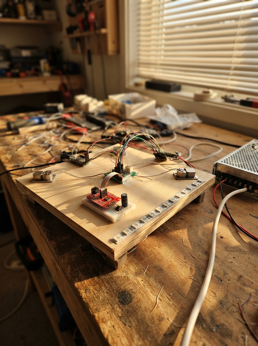
This smart gait analysis platform uses four load cells mounted under a walking surface to detect and count footsteps in real time. The system combines an Arduino Uno with an ESP32 for data processing and telemetry, using the HX711 amplifier to read weight changes with high precision. A perimeter of addressable RGB LEDs provides visual feedback, while a buzzer and push button enable user interaction and calibration.
Builders will receive a complete wiring diagram showing how to connect the load cells to the combinator board and HX711, integrate the feedback components, and establish safe communication between the microcontrollers. The guide includes a parts list, step-by-step assembly instructions for the protected platform, and Arduino firmware that detects step events, filters sensor noise, and streams telemetry data to the ESP32 for logging or analysis.
Wiring diagram

Gather all the parts
Assemble it in 6 steps
1. Build the protected walking platform
Make a rigid 130 cm by 80 cm structural base. Place one 50 kg half-bridge load cell at each corner with its sensing end oriented exactly as shown by its seller’s drawing. Mount the acrylic sheet so it presses evenly on all four sensor points, then attach the 4 cm EVA foam mat on top. Leave the electronics accessible at one edge.
- The top plate must not touch the base anywhere except through the four load-cell sensing points, or the weight reading will be wrong.
- Use mechanical stops that prevent more than the load-cell travel, but leave a small clearance so normal standing weight still reaches the sensors.
- Do not stand on the platform until the acrylic sheet is supported evenly by all four load cells; an uneven or hard mechanical stop can permanently bend a sensor.
2. Join the four load cells to the weighing board
Use the supplied four-cell junction board to combine the four half-bridge load cells into one full bridge. From that junction board, connect E+ to HX711 E+, E- to HX711 E-, A+ to HX711 A+, and A- to HX711 A-. Keep these four signal wires twisted or bundled and away from the LED power wires.
- Label each corner cable before closing the platform so a damaged sensor can be traced later.
- If pressing one corner makes the reading move the wrong way or gives nearly zero change, re-check the junction-board wiring diagram for that load-cell color set.
- Do not guess load-cell wire colors: different sellers use different colors, and a wrong bridge connection prevents reliable weighing.
3. Wire the Mega’s sensors and feedback parts
Connect HX711 VCC to the 5V rail (power), HX711 GND to GND (ground), HX711 DT to Mega D3 (weight data), and HX711 SCK to Mega D2 (clock). Connect the tare pushbutton with one leg to Mega D4 (signal) and the other leg to GND (ground). Connect the piezo buzzer signal lead to Mega D5 (sound signal) and its other lead to GND (ground).
- The button uses the Mega’s built-in pull-up, so it needs no extra resistor.
- Use a small active piezo buzzer or passive piezo disc that can be driven from a logic pin; do not connect a large speaker directly to D5.
- Make sure the buzzer and HX711 grounds reach the same GND rail as the Mega, otherwise readings and sound feedback can behave erratically.
4. Install the perimeter LEDs safely
Mount no more than 60 WS2812B LEDs around the underside perimeter of the acrylic. Connect strip 5V to the 5V rail (power) and strip GND to GND (ground). Put the 1000 µF capacitor across the strip input: its long positive lead to 5V and its striped negative lead to GND. Connect Mega D6 through the 330 Ω resistor to the strip DIN pad (data).
- Follow the arrow printed on the strip: Mega data must enter the DIN end, not the DOUT end.
- Inject the 5V and GND supply at the strip input with adequately thick wire; do not route LED power through the Mega board.
- Do not swap the capacitor leads — a reversed electrolytic capacitor can heat up or burst.
- Never power the LED strip without a common ground to the Mega; the data signal needs that shared reference.
5. Wire the protected Mega-to-ESP32 link
Connect Mega D18 (Serial1 TX) to one end of the 1 kΩ resistor. At its other end, make a junction with ESP32 GPIO16/RX2 and one end of the 2 kΩ resistor. Connect the remaining 2 kΩ resistor end to GND. This divider reduces the Mega’s 5 V serial signal to a safe ESP32-level signal. Connect Mega GND and ESP32 GND together.
- This project only sends data from Mega to ESP32, so do not connect an ESP32 transmit pin back to Mega pin 19.
- Keep the two divider resistors near the ESP32 input pin.
- Do not connect Mega D18 directly to ESP32 GPIO16; the Mega sends 5 V logic and that can damage the ESP32’s 3.3 V input.
6. Connect the enclosed 5 V power distribution
With mains power disconnected, connect the regulated supply’s +5V output to the Mega 5V pin, ESP32 5V/VIN pin, HX711 VCC, and LED-strip 5V input. Connect supply GND to Mega GND, ESP32 GND, HX711 GND, buzzer ground, button ground, and LED-strip GND. Put the power supply inside a closed grounded enclosure and use a fused, strain-relieved mains cable.
- Use a terminal block or fused distribution block for the 5V and GND branches rather than stacking many wires in one screw terminal.
- Before connecting the boards, use a multimeter to confirm the supply output is close to 5 V and the polarity is correct.
- Mains wiring can injure or kill. Have a qualified person install the AC input, fuse, enclosure earth connection, and strain relief; do not leave mains terminals exposed.
- Do not connect USB power to either controller while the external 5 V rail is also connected unless the board’s power arrangement has been specifically made safe for it.
Review all connections
1. Connections between "power_supply_1" and "Arduino"
2. Connections between "load_cells_1" and "Arduino"
3. Connections between "hx711_1" and "Arduino"
4. Connections between "led_strip_1" and "Arduino"
5. Connections between "led_data_resistor_1" and "Arduino"
6. Connections between "led_bulk_capacitor_1" and "Arduino"
7. Connections between "tare_button_1" and "Arduino"
8. Connections between "buzzer_1" and "Arduino"
9. Connections between "esp32_telemetry_1" and "Arduino"
10. Connections between "uart_divider_top_1" and "Arduino"
11. Connections between "uart_divider_bottom_1" and "Arduino"
Deploy the firmware
#include <Arduino.h>
#include <HX711.h>
#include <Adafruit_NeoPixel.h>


// Forward declarations
void showIdle();
void showStep();
void showTare();
void readTareButton(uint32_t now);
void updateWeight(uint32_t now);
void sendTelemetry(uint32_t now);

constexpr uint8_t HX711_SCK_PIN = 2;
constexpr uint8_t HX711_DT_PIN = 3;
constexpr uint8_t TARE_BUTTON_PIN = 4;
constexpr uint8_t BUZZER_PIN = 5;
constexpr uint8_t LED_PIN = 6;
constexpr uint16_t LED_COUNT = 60;

// Calibrate this number after installation. It is raw HX711 counts per kilogram.
constexpr float CALIBRATION_FACTOR = -21000.0f;
constexpr float STEP_ON_KG = 5.0f;
constexpr float STEP_OFF_KG = 2.0f;
constexpr uint16_t SAMPLE_INTERVAL_MS = 50;
constexpr uint16_t TELEMETRY_INTERVAL_MS = 100;
constexpr uint16_t BUTTON_DEBOUNCE_MS = 35;

HX711 scale;
Adafruit_NeoPixel pixels(LED_COUNT, LED_PIN, NEO_GRB + NEO_KHZ800);

bool footOnPlatform = false;
bool lastButtonReading = HIGH;
bool stableButtonState = HIGH;
uint32_t lastButtonChangeMs = 0;
uint32_t lastSampleMs = 0;
uint32_t lastTelemetryMs = 0;
uint32_t stepCount = 0;
float filteredKg = 0.0f;

void showIdle() {
  for (uint16_t i = 0; i < LED_COUNT; ++i) pixels.setPixelColor(i, pixels.Color(0, 8, 0));
  pixels.show();
}

void showStep() {
  for (uint16_t i = 0; i < LED_COUNT; ++i) {
    uint8_t level = 22 + ((i % 8) * 3);
    pixels.setPixelColor(i, pixels.Color(0, level, 0));
  }
  pixels.show();
}

void showTare() {
  for (uint16_t i = 0; i < LED_COUNT; ++i) pixels.setPixelColor(i, pixels.Color(0, 0, 32));
  pixels.show();
  tone(BUZZER_PIN, 1200, 120);
}

void readTareButton(uint32_t now) {
  bool reading = digitalRead(TARE_BUTTON_PIN);
  if (reading != lastButtonReading) lastButtonChangeMs = now;
  if ((now - lastButtonChangeMs) > BUTTON_DEBOUNCE_MS && reading != stableButtonState) {
    stableButtonState = reading;
    if (stableButtonState == LOW) {
      scale.tare(20);
      filteredKg = 0.0f;
      footOnPlatform = false;
      stepCount = 0;
      showTare();
    }
  }
  lastButtonReading = reading;
}

void updateWeight(uint32_t now) {
  if (now - lastSampleMs < SAMPLE_INTERVAL_MS || !scale.is_ready()) return;
  lastSampleMs = now;
  float kg = scale.get_units(3);
  if (kg > -0.15f && kg < 0.15f) kg = 0.0f;
  if (kg < 0.0f) kg = 0.0f;
  filteredKg = (filteredKg * 0.75f) + (kg * 0.25f);

  if (!footOnPlatform && filteredKg >= STEP_ON_KG) {
    footOnPlatform = true;
    ++stepCount;
    tone(BUZZER_PIN, 880, 90);
    showStep();
  } else if (footOnPlatform && filteredKg <= STEP_OFF_KG) {
    footOnPlatform = false;
    noTone(BUZZER_PIN);
    showIdle();
  }
}

void sendTelemetry(uint32_t now) {
  if (now - lastTelemetryMs < TELEMETRY_INTERVAL_MS) return;
  lastTelemetryMs = now;
  // CSV protocol: milliseconds,kg,foot_present,step_count\n
  Serial1.print(now);
  Serial1.print(',');
  Serial1.print(filteredKg, 2);
  Serial1.print(',');
  Serial1.print(footOnPlatform ? 1 : 0);
  Serial1.print(',');
  Serial1.println(stepCount);
}

void setup() {
  pinMode(TARE_BUTTON_PIN, INPUT_PULLUP);
  pinMode(BUZZER_PIN, OUTPUT);
  Serial.begin(115200);
  Serial1.begin(115200);
  scale.begin(HX711_DT_PIN, HX711_SCK_PIN);
  scale.set_scale(CALIBRATION_FACTOR);
  scale.tare(20);
  pixels.begin();
  pixels.setBrightness(32); // Caps strip draw well below the 5 A supply limit.
  showIdle();
}

void loop() {
  uint32_t now = millis();
  readTareButton(now);
  updateWeight(now);
  sendTelemetry(now);
}
Remix this project
Make it yours in one click
Open a full copy of this project in your own Schematik workspace — diagram, code, parts, and assembly steps included. Swap the sensor, add features, or redesign the whole thing with AI. The author's original stays untouched.
Related projects
Soldering Stand with Fume Extractor and Lighting
Arduino · September 22, 2026prahaladh.pradeep
Multisensor Home Safety Alert System
Arduino · September 22, 2026SHIVΞSH
Automatische Pflanzenbewässerungskontrolle
Arduino · September 22, 2026michael.hasenberg