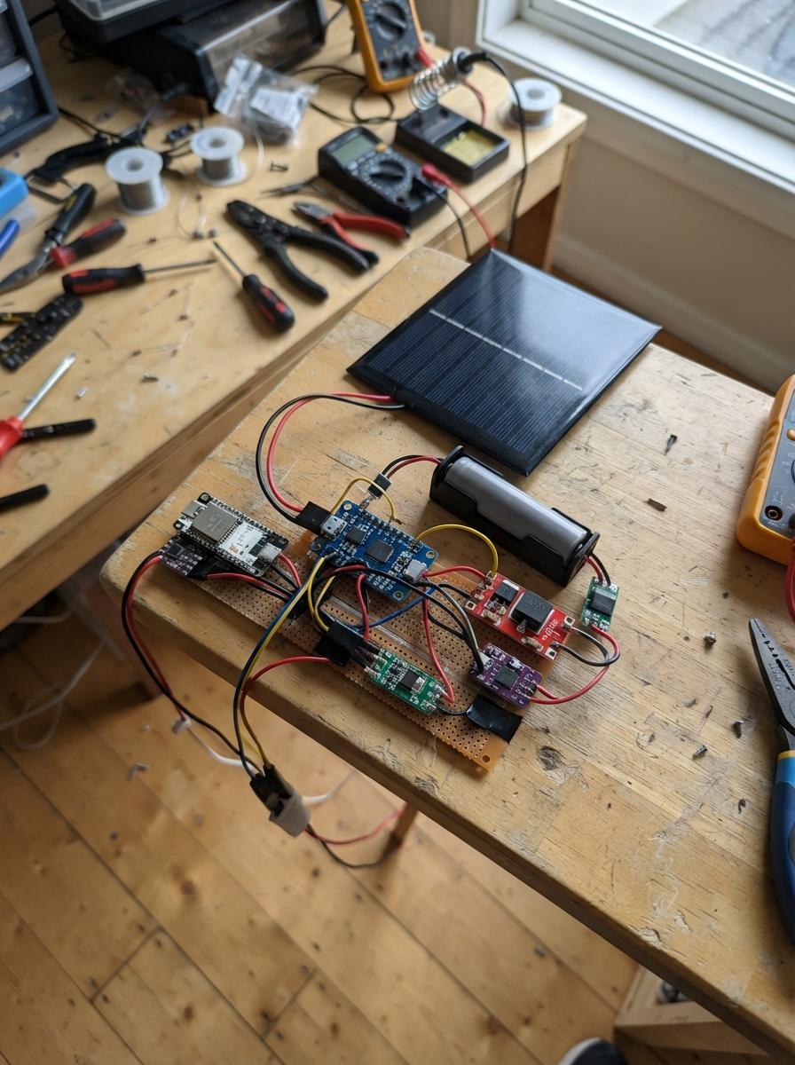
The Solar IoT Paddi Water Monitor is a remote sensing system that tracks water levels in rice paddies using an ultrasonic sensor, powered by a solar-charged battery pack and connected via LTE. The ESP32 microcontroller collects water depth, battery voltage, temperature, and signal strength at 30-minute intervals, queuing up to 12 hours of readings for reliable transmission even in areas with intermittent connectivity.
This guide provides a complete wiring diagram, detailed parts list, and step-by-step assembly instructions for building the monitor from discrete components. Included firmware handles solar charging management, sensor operation, real-time clock synchronization, and HTTPS uploads to a cloud dashboard, with all configuration points clearly marked for field deployment.
Wiring diagram
Gather all the parts
Assemble it in 7 steps
1. Prepare the water tube and reference mark
Push a straight 75 mm perforated PVC observation tube into the paddy soil so its marked zero line is exactly at the soil surface. Drill 6–8 mm holes every 5 cm only along the lower 70 cm, add a gravel-free cap at the bottom, and leave the top high enough that floodwater cannot enter the electronics box.
- Put the zero mark on the outside of the tube and photograph it during installation; that is the reference used by the firmware.
- Do not put holes near the sensor at the top, because insects, splashing water, and mud can disturb the sound path.
2. Fit the ultrasonic sensor in the top cap
Fit the sealed JSN-SR04T transducer centrally into a removable PVC top cap, with its face pointing straight down the tube. Set the sensor face 55 cm above the soil-zero mark; this gives a 25 cm distance at +30 cm water and about 75 cm at −20 cm water.
- Use the same 55 cm dimension in every node, or change SENSOR_ZERO_HEIGHT_CM in the firmware before deployment.
- Keep the sound path clear. A tilted sensor, spider web, condensation droplet, or floating rice residue can make the reading wrong.
3. Build the protected battery pack
Use two identical, new, protected 3500 mAh 18650 cells permanently connected in parallel, then connect their joined positive ends to battery_bms B+ and joined negative ends to B−. Connect battery_bms P+ and P− only to the charger and electronics power bus.
- Match brand, capacity, age, and state of charge before making a parallel pack.
- Do not mix old and new cells or connect cells with different voltages together; a large equalising current can overheat the cells.
4. Wire the solar charging input
Connect solar_panel V+ to solar_charger VBUS and connect solar_panel GND to GND. Connect solar_tvs with its striped cathode end to the same solar positive point and its other end to GND. Connect the battery-protection P+ and P− terminals to solar_charger LIPO and GND_3.
- Tape the NTC probe tightly against the side of one battery cell with Kapton tape, then insulate over it so the charger sees cell temperature rather than hot enclosure air.
- Make sure V+ and GND are not swapped; swapped solar power can damage the charger. Use a charger board whose THERM setting is verified for a 10 kΩ NTC and stops charging below 0°C.
5. Wire the regulated power and modem burst capacitor
Connect the protected battery bus to logic_regulator VIN and modem_boost VIN. Set logic_regulator to exactly 3.3 V before attaching the ESP32 board. Set modem_boost to exactly 5.0 V with a meter, connect it through modem_switch to lte_modem VCC, and place modem_bulk_cap directly across modem VCC and GND with its + leg on VCC.
- Use short, thick wires for the battery-to-boost-to-modem path; the capacitor leads should be as short as possible.
- The capacitor is polarised: its minus-striped lead goes to GND. Reversing it can make it burst. Do not power the modem from the ESP32 5 V or 3.3 V pin.
6. Connect the controller, sensor, and clock
Connect the 3.3 V rail to the ESP32 3V3 pin, the RTC VIN, both load-switch VBIAS pins, and the temperature sensor reference. Connect all GND pins together. Connect the RTC SDA to GPIO8 and SCL to GPIO9. Connect the sensor TRIG to GPIO4; route its ECHO through echo_level_shifter and then to GPIO5. Connect sensor_switch ON to GPIO6, modem_boost EN to GPIO14, modem_switch ON to GPIO15, modem PWRKEY to GPIO21, modem TXD to GPIO44, modem RXD to GPIO43, battery_divider OUT to GPIO1, temperature SIG to GPIO2, and charger CHG to GPIO3.
- The echo divider is essential because the ultrasonic module can send a 5 V echo pulse; GPIO5 must only see the divided 3.3 V-safe signal.
- Make sure VCC and GND are not swapped on the sensor or RTC; swapped power can damage the small boards.
7. Install the box, solar panel, and antenna
Mount all electronics on standoffs inside an IP67 UV-stable polycarbonate box. Run the solar, sensor, and antenna cables through IP68 cable glands with drip loops. Mount the solar panel facing south with a 15–25° tilt, and mount the LTE antenna vertically on a 1.5–2 m non-metallic pole above the rice canopy and at least 30 cm from the solar panel and enclosure.
- Add a hydrophobic IP67 vent plug low on the enclosure wall and a small desiccant pouch inside. Use metal mesh or conduit over exposed cables where rodents are present.
- Do not place the LTE antenna inside a metal enclosure or directly against the solar panel; this can reduce signal strength and waste battery power.
Review all connections
1. Connections between "solar_panel" and "ESP32"
2. Connections between "solar_tvs" and "ESP32"
3. Connections between "solar_charger" and "ESP32"
4. Connections between "battery_cell_1" and "ESP32"
5. Connections between "battery_cell_2" and "ESP32"
6. Connections between "battery_bms" and "ESP32"
7. Connections between "logic_regulator" and "ESP32"
8. Connections between "modem_boost" and "ESP32"
9. Connections between "modem_switch" and "ESP32"
10. Connections between "sensor_switch" and "ESP32"
11. Connections between "lte_modem" and "ESP32"
12. Connections between "modem_bulk_cap" and "ESP32"
13. Connections between "water_sensor" and "ESP32"
14. Connections between "rtc" and "ESP32"
15. Connections between "ambient_ntc" and "ESP32"
16. Connections between "battery_divider" and "ESP32"
17. Connections between "echo_level_shifter" and "ESP32"
Deploy the firmware
#include <Arduino.h>
#include <Wire.h>
#include <RTClib.h>
#include <Preferences.h>
#include <math.h>

// Commission these three values for the SIM and central dashboard before field deployment.
static const char APN[] = "YOUR_APN";
static const char HTTPS_URL[] = "https://your-cloud.example/api/v1/water-level";
static const char DEVICE_ID[] = "paddy-node-001";

constexpr int BATTERY_ADC_PIN = 1;
constexpr int NTC_ADC_PIN = 2;
constexpr int CHARGE_STATUS_PIN = 3;
constexpr int ULTRASONIC_TRIG_PIN = 4;
constexpr int ULTRASONIC_ECHO_PIN = 5;
constexpr int SENSOR_SWITCH_PIN = 6;
constexpr int MODEM_BOOST_EN_PIN = 14;
constexpr int MODEM_SWITCH_EN_PIN = 15;
// ESP32-S3 routes UART signals through its GPIO matrix; these avoid the board's USB/console pins.
constexpr int MODEM_RX_PIN = 18;
constexpr int MODEM_TX_PIN = 17;
constexpr int MODEM_PWRKEY_PIN = 21;
constexpr int I2C_SDA_PIN = 8;
constexpr int I2C_SCL_PIN = 9;

constexpr uint64_t SAMPLE_INTERVAL_US = 30ULL * 60ULL * 1000000ULL;
constexpr uint8_t UPLOAD_EVERY_SAMPLES = 6;  // 3 hours; change to 12 for 6 hours.
constexpr uint8_t QUEUE_SLOTS = 24;          // Holds 12 hours of 30-minute records.
constexpr float SENSOR_ZERO_HEIGHT_CM = 55.0f;
// The sensor face is fixed 55 cm above the soil-zero reference. A distance of 25 cm is +30 cm water.

HardwareSerial modem(1);
RTC_DS3231 rtc;
Preferences prefs;

struct Reading {
  float waterLevelCm;
  float batteryV;
  float temperatureC;
  int rssi;
  bool charging;
  DateTime timestamp;
};

static void setLoadPower(bool on) {
  digitalWrite(MODEM_BOOST_EN_PIN, on ? HIGH : LOW);
  digitalWrite(MODEM_SWITCH_EN_PIN, on ? HIGH : LOW);
  digitalWrite(SENSOR_SWITCH_PIN, on ? HIGH : LOW);
  if (on) delay(250);
}

static float readBatteryV() {
  // Divider is 100k/100k, so ADC pin voltage is half battery voltage.
  uint32_t raw = analogReadMilliVolts(BATTERY_ADC_PIN);
  return (raw * 2.0f) / 1000.0f;
}

static float readNtcC() {
  // 10k B3950 NTC, 10k fixed resistor to 3.3 V. Return NAN if wiring is open/shorted.
  uint32_t mv = analogReadMilliVolts(NTC_ADC_PIN);
  if (mv < 20 || mv > 3280) return NAN;
  const float v = mv / 1000.0f;
  const float resistance = 10000.0f * v / (3.3f - v);
  const float kelvin = 1.0f / ((1.0f / 298.15f) + logf(resistance / 10000.0f) / 3950.0f);
  return kelvin - 273.15f;
}

static float readDistanceCm() {
  digitalWrite(ULTRASONIC_TRIG_PIN, LOW);
  delay(5);
  digitalWrite(ULTRASONIC_TRIG_PIN, HIGH);
  delayMicroseconds(12);
  digitalWrite(ULTRASONIC_TRIG_PIN, LOW);
  const uint32_t pulse = pulseIn(ULTRASONIC_ECHO_PIN, HIGH, 45000UL);
  if (pulse == 0) return NAN;
  return pulse / 58.0f;
}

static float filteredWaterLevelCm() {
  float sum = 0.0f;
  uint8_t valid = 0;
  for (uint8_t i = 0; i < 5; ++i) {
    const float distance = readDistanceCm();
    if (!isnan(distance) && distance >= 25.0f && distance <= 100.0f) {
      sum += distance;
      ++valid;
    }
    delay(80);
  }
  if (valid < 3) return NAN;
  const float distance = sum / valid;
  return SENSOR_ZERO_HEIGHT_CM - distance;
}

static bool atCommand(const String &command, const char *expected, uint32_t timeoutMs, String *reply = nullptr) {
  while (modem.available()) modem.read();
  modem.println(command);
  String response;
  const uint32_t started = millis();
  while (millis() - started < timeoutMs) {
    while (modem.available()) response += static_cast<char>(modem.read());
    if (response.indexOf(expected) >= 0) {
      if (reply != nullptr) *reply = response;
      return true;
    }
    delay(10);
  }
  if (reply != nullptr) *reply = response;
  return false;
}

static int modemRssi() {
  String reply;
  if (!atCommand("AT+CSQ", "OK", 2500, &reply)) return -1;
  const int colon = reply.indexOf(':');
  const int comma = reply.indexOf(',', colon + 1);
  if (colon < 0 || comma < 0) return -1;
  const int csq = reply.substring(colon + 1, comma).toInt();
  if (csq == 99) return -1;
  return -113 + (2 * csq); // 3GPP CSQ to dBm approximation.
}

static bool modemStart() {
  setLoadPower(true);
  modem.begin(115200, SERIAL_8N1, MODEM_RX_PIN, MODEM_TX_PIN);
  pinMode(MODEM_PWRKEY_PIN, OUTPUT);
  digitalWrite(MODEM_PWRKEY_PIN, LOW);
  delay(1200);
  digitalWrite(MODEM_PWRKEY_PIN, HIGH);
  for (uint8_t tries = 0; tries < 12; ++tries) {
    if (atCommand("AT", "OK", 1500)) return true;
    delay(1000);
  }
  return false;
}

static void modemStop() {
  atCommand("AT+HTTPTERM", "OK", 1500);
  modem.end();
  setLoadPower(false);
}

static bool postJsonTls(const String &json) {
  // SIM7600 HTTPS AT sequence. The deployed SIM profile must permit packet data and TLS.
  if (!atCommand("AT+CGDCONT=1,\"IP\",\"" + String(APN) + "\"", "OK", 3000)) return false;
  if (!atCommand("AT+CGATT=1", "OK", 30000)) return false;
  if (!atCommand("AT+HTTPINIT", "OK", 4000)) return false;
  if (!atCommand("AT+HTTPPARA=\"CID\",1", "OK", 3000)) return false;
  if (!atCommand("AT+HTTPSSL=1", "OK", 3000)) return false;
  if (!atCommand("AT+HTTPPARA=\"URL\",\"" + String(HTTPS_URL) + "\"", "OK", 5000)) return false;
  if (!atCommand("AT+HTTPPARA=\"CONTENT\",\"application/json\"", "OK", 3000)) return false;
  if (!atCommand("AT+HTTPDATA=" + String(json.length()) + ",10000", "DOWNLOAD", 5000)) return false;
  modem.print(json);
  delay(200);
  return atCommand("AT+HTTPACTION=1", "+HTTPACTION: 1,2", 45000);
}

static String toJson(const Reading &r) {
  char stamp[25];
  snprintf(stamp, sizeof(stamp), "%04d-%02d-%02dT%02d:%02d:%02dZ", r.timestamp.year(), r.timestamp.month(), r.timestamp.day(), r.timestamp.hour(), r.timestamp.minute(), r.timestamp.second());
  String json = "{\"device_id\":\"" + String(DEVICE_ID) + "\",\"timestamp\":\"" + String(stamp) + "\",\"water_level_cm\":";
  json += isnan(r.waterLevelCm) ? "null" : String(r.waterLevelCm, 1);
  json += ",\"battery_v\":" + String(r.batteryV, 3);
  json += ",\"temp_c\":" + (isnan(r.temperatureC) ? String("null") : String(r.temperatureC, 1));
  json += ",\"rssi\":" + String(r.rssi);
  json += ",\"charging\":" + String(r.charging ? "true" : "false") + "}";
  return json;
}

static void queueRecord(const String &json) {
  const uint8_t head = prefs.getUChar("head", 0);
  prefs.putString(("q" + String(head)).c_str(), json);
  prefs.putUChar("head", (head + 1) % QUEUE_SLOTS);
  uint8_t count = prefs.getUChar("count", 0);
  if (count < QUEUE_SLOTS) ++count;
  prefs.putUChar("count", count);
}

static void publishQueued() {
  uint8_t count = prefs.getUChar("count", 0);
  uint8_t head = prefs.getUChar("head", 0);
  uint8_t tail = (head + QUEUE_SLOTS - count) % QUEUE_SLOTS;
  while (count > 0) {
    const String key = "q" + String(tail);
    const String json = prefs.getString(key.c_str(), "");
    if (json.length() == 0 || !postJsonTls(json)) break;
    prefs.remove(key.c_str());
    tail = (tail + 1) % QUEUE_SLOTS;
    --count;
    prefs.putUChar("count", count);
  }
}

void setup() {
  pinMode(SENSOR_SWITCH_PIN, OUTPUT);
  pinMode(MODEM_BOOST_EN_PIN, OUTPUT);
  pinMode(MODEM_SWITCH_EN_PIN, OUTPUT);
  pinMode(ULTRASONIC_TRIG_PIN, OUTPUT);
  pinMode(ULTRASONIC_ECHO_PIN, INPUT);
  pinMode(CHARGE_STATUS_PIN, INPUT_PULLUP);
  setLoadPower(false);

  analogReadResolution(12);
  Wire.begin(I2C_SDA_PIN, I2C_SCL_PIN);
  rtc.begin();
  prefs.begin("paddy", false);

  // Power only the sensor path for the five-sample measurement burst.
  digitalWrite(MODEM_BOOST_EN_PIN, HIGH);
  digitalWrite(SENSOR_SWITCH_PIN, HIGH);
  delay(250);
  Reading reading;
  reading.waterLevelCm = filteredWaterLevelCm();
  reading.batteryV = readBatteryV();
  reading.temperatureC = readNtcC();
  reading.charging = digitalRead(CHARGE_STATUS_PIN) == LOW;
  reading.timestamp = rtc.now();
  digitalWrite(SENSOR_SWITCH_PIN, LOW);
  digitalWrite(MODEM_BOOST_EN_PIN, LOW);
  reading.rssi = -1;

  uint8_t sampleCount = prefs.getUChar("samples", 0) + 1;
  bool shouldUpload = sampleCount >= UPLOAD_EVERY_SAMPLES;
  if (shouldUpload) sampleCount = 0;
  prefs.putUChar("samples", sampleCount);

  if (shouldUpload && modemStart()) {
    reading.rssi = modemRssi();
    queueRecord(toJson(reading));
    publishQueued();
    modemStop();
  } else {
    queueRecord(toJson(reading));
  }

  prefs.end();
  esp_sleep_enable_timer_wakeup(SAMPLE_INTERVAL_US);
  delay(50);
  esp_deep_sleep_start();
}

void loop() {
  // setup() always enters deep sleep; loop is intentionally never reached.
}
Remix this project
Make it yours in one click
Open a full copy of this project in your own Schematik workspace, diagram, code, parts, and assembly steps included. Swap the sensor, add features, or redesign the whole thing with AI. The author's original stays untouched.