Community project
Solar Mosquito Surveillance
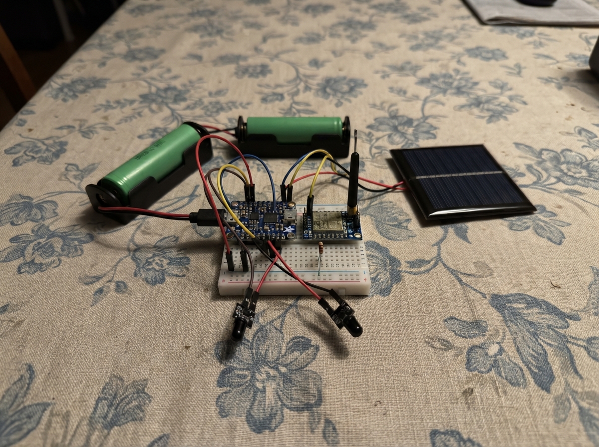
This project deploys an autonomous mosquito trap monitor that uses an infrared break-beam sensor to count insect passages and reports detections over long-range LoRa radio. The system runs on an ESP32 microcontroller powered by a solar panel and rechargeable battery, enabling weeks of field operation without maintenance or external power.
Builders will receive a complete wiring diagram, parts list, and step-by-step assembly instructions for constructing a weatherproof trap unit with LoRa connectivity. The included Arduino firmware handles beam detection, crossing counting with debouncing, and periodic status reports transmitted at 915 MHz. Each trap can be assigned a unique node ID for multi-unit deployments, allowing distributed mosquito population monitoring across large areas.
Wiring diagram
Gather all the parts
Assemble it in 6 steps
1. Prepare the weatherproof enclosure and trap tunnel
Make a shaded, rain-sheltered enclosure with a narrow entry tunnel and a removable dark water-lure chamber below it. Place the electronics in a separate sealed upper compartment so water, insects, and lure liquid cannot reach the board.
- Use insect mesh or a drain hole where needed so rain cannot turn the lure chamber into an uncontrolled breeding site.
- The infrared beam should cross the entry tunnel, not shine into the lure liquid.
- Do not leave standing water unmanaged; service the trap on a regular schedule so it does not become a mosquito breeding site.
2. Fit the infrared beam pair
Mount the infrared transmitter and receiver directly opposite each other across the tunnel, with a clear straight path between their dark sensor windows. Connect the break-beam VCC pin to 3V3 (power), GND to GND (ground), and OUT to GPIO25 (signal). Put the 10 kΩ resistor between 3V3 (power) and the same OUT/GPIO25 connection (keeps the signal steady when the beam is clear).
- Keep the two sensor windows aligned; a small tube around each window helps block sunlight.
- Test by passing a thin card through the tunnel: the board should count one crossing after firmware is deployed.
- Make sure VCC and GND are not swapped — swapped power can damage the sensor.
3. Wire the LoRa radio and antenna
Connect the LoRa module VCC to 3V3 (power), GND to GND (ground), MOSI to GPIO23 (data), MISO to GPIO19 (data), SCK to GPIO18 (clock), NSS to GPIO4 (radio select), RESET to GPIO27 (reset signal), and DIO0 to GPIO26 (radio message signal). Screw on or connect a 915 MHz antenna before applying power.
- Keep the antenna outside the metal enclosure or use a bulkhead antenna lead.
- Keep the radio and its antenna lead away from the sensor wires where possible.
- Never transmit with no antenna connected — that can damage the radio module.
- This 3.3 V radio must never be connected to 5 V power or 5 V logic signals.
4. Connect the solar charging parts
Connect the solar panel positive lead to the charger VIN pin (solar charging power) and its negative lead to charger GND (ground). Put the 18650 cell in its holder, then connect holder BAT+ to the cell positive terminal and holder BAT- to the cell negative terminal. Connect cell positive to charger BAT (battery charging connection) and cell negative to charger GND (ground).
- Mount the panel where it receives several hours of direct daylight and angle it so rain runs off.
- Use a protected, rechargeable 18650 Li-ion cell from a reputable supplier.
- Never use a disposable AA, alkaline, or non-rechargeable cell in this charger — charging the wrong battery can cause fire or injury.
- Check the positive and negative markings before connecting the battery; reversed battery wiring can damage the charger and battery.
5. Power the ESP32 from the regulated output
Connect the charger board 3V3 pin to the ESP32 3V3 pin (regulated power) and charger GND to an ESP32 GND pin (common ground). All sensor and radio grounds must share this same GND connection.
- For the first test, you can power the ESP32 by USB while leaving the solar system disconnected, then move to the solar 3V3 supply after checking the wiring.
- Do not feed the charger board’s 3.3 V output into the ESP32 VIN or 5V pin — use the ESP32 3V3 pin only.
6. Install and test the field unit
Place the board in the dry electronics compartment, close the enclosure, connect the antenna, then place the solar panel in sunlight. Configure your receiving gateway for raw LoRa at 915.0 MHz with the same standard LoRa settings used by this node, then watch for a boot packet beginning with node=TRAP-001.
- Change TRAP-001 in the firmware before deploying a second trap so the reports can be told apart.
- A crossing is an activity indicator only; manually inspect catches if you need mosquito or species counts.
- This design sends raw LoRa packets, not LoRaWAN packets; a LoRaWAN-only gateway configuration will not decode them.
Review all connections
1. Connections between "solar_panel" and "ESP32"
2. Connections between "battery_holder" and "ESP32"
3. Connections between "battery_cell" and "ESP32"
4. Connections between "solar_charger" and "ESP32"
5. Connections between "lora_915" and "ESP32"
6. Connections between "ir_gate" and "ESP32"
7. Connections between "beam_pullup" and "ESP32"
Deploy the firmware
#include <Arduino.h>
#include <SPI.h>
#include <LoRa.h>

// Give every deployed trap a different number before field installation.
static const char* NODE_ID = "TRAP-001";

static const int LORA_SCK = 18;
static const int LORA_MISO = 19;
static const int LORA_MOSI = 23;
static const int LORA_CS = 4;
static const int LORA_RESET = 27;
static const int LORA_DIO0 = 26;
static const int BEAM_PIN = 25;

static const long LORA_FREQUENCY_HZ = 915000000L;
static const unsigned long REPORT_INTERVAL_MS = 600000UL; // 10 minutes
static const unsigned long CROSSING_LOCKOUT_MS = 350UL;

volatile bool beamEdgeSeen = false;
volatile unsigned long beamEdgeAtMs = 0;
uint32_t crossingCount = 0;
unsigned long lastAcceptedCrossingMs = 0;
unsigned long lastReportMs = 0;
bool radioReady = false;

void IRAM_ATTR onBeamBroken() {
  beamEdgeSeen = true;
  beamEdgeAtMs = millis();
}

bool sendReport(const char* eventName) {
  if (!radioReady) {
    return false;
  }

  String packet = String("node=") + NODE_ID +
                  ",event=" + eventName +
                  ",crossings=" + String(crossingCount) +
                  ",uptime_s=" + String(millis() / 1000UL);

  LoRa.beginPacket();
  LoRa.print(packet);
  int result = LoRa.endPacket();
  Serial.print("LoRa report: ");
  Serial.println(packet);
  return result == 1;
}

void setup() {
  Serial.begin(115200);
  delay(100);

  pinMode(BEAM_PIN, INPUT);
  attachInterrupt(digitalPinToInterrupt(BEAM_PIN), onBeamBroken, FALLING);

  SPI.begin(LORA_SCK, LORA_MISO, LORA_MOSI, LORA_CS);
  LoRa.setPins(LORA_CS, LORA_RESET, LORA_DIO0);
  radioReady = LoRa.begin(LORA_FREQUENCY_HZ);

  if (radioReady) {
    LoRa.setTxPower(17);
    LoRa.idle();
    sendReport("boot");
  } else {
    Serial.println("LoRa radio was not detected. Check 3.3V power, SPI wires, and antenna.");
  }

  lastReportMs = millis();
}

void loop() {
  bool countThisEdge = false;
  noInterrupts();
  if (beamEdgeSeen) {
    beamEdgeSeen = false;
    countThisEdge = true;
  }
  interrupts();

  if (countThisEdge) {
    const unsigned long now = millis();
    if (now - lastAcceptedCrossingMs >= CROSSING_LOCKOUT_MS) {
      crossingCount++;
      lastAcceptedCrossingMs = now;
      Serial.print("Beam crossing count: ");
      Serial.println(crossingCount);
    }
  }

  const unsigned long now = millis();
  if (now - lastReportMs >= REPORT_INTERVAL_MS) {
    sendReport("periodic");
    lastReportMs = now;
  }

  delay(10);
}
Remix this project
Make it yours in one click
Open a full copy of this project in your own Schematik workspace — diagram, code, parts, and assembly steps included. Swap the sensor, add features, or redesign the whole thing with AI. The author's original stays untouched.