Community project
Soldering Stand with Fume Extractor and Lighting
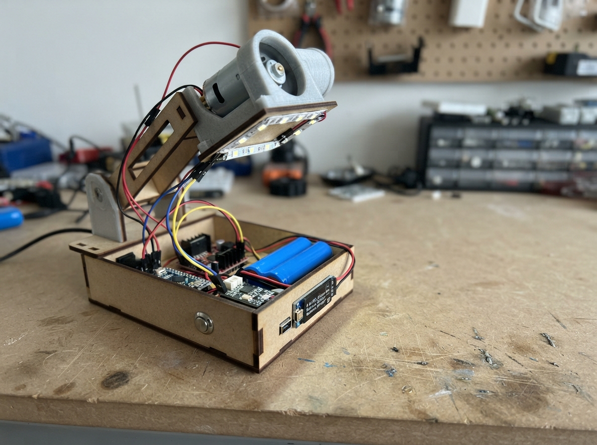
This soldering stand combines a motorized fume extractor with Arduino-controlled lighting and power management. The project uses a brushed DC motor to drive the extraction fan, a WS2812B RGB LED for status indication, and a push button to toggle operation. A 2S lithium-ion battery pack with protection circuitry provides portable power, while a buck converter steps voltage down for the Arduino and motor driver.
This guide includes a complete wiring diagram, parts list with battery specifications, Arduino firmware with debounced button control and LED status feedback, and step-by-step assembly instructions. Builders will learn how to integrate motor control, power protection, and visual feedback into a practical maker tool, with safe battery handling and charging procedures throughout.
Wiring diagram

Gather all the parts
Assemble it in 6 steps
1. Prepare the two-cell battery pack
Use two identical 4300 mAh 18650 cells of the same age and charge level in a proper 2-cell holder or a preassembled 2S pack. Connect the pack negative end to B- on bms_1, the link between the two cells to B1, and the pack positive end to B+.
- Keep the two cells together as one pair; do not mix one new cell with one older cell.
- Use insulated holders or welded packs rather than loose cells and improvised wires.
- Never connect the cells directly to the Arduino or motor driver — a full pack is 8.4 V and can damage the 6 V motor.
- A short circuit across an 18650 cell can make wires dangerously hot or cause fire; work with the cells removed until the wiring is checked.
2. Add protected power and charging
Connect P+ on bms_1 to VIN+ on buck_1 and P- on bms_1 to VIN-. Connect charger_1 OUT+ to BMS P+ and charger_1 OUT- to BMS P-. The charger connects to P+ and P- so the protection board remains in the circuit while charging.
- Use an 8.4 V charger specifically labelled for a two-cell lithium-ion pack.
- Leave the charger unplugged while making the rest of the wiring.
- Do not use a single-cell USB lithium charger or a 5 V phone charger directly on this pack — it will not charge two series cells safely.
- Never swap the charger leads; reversed charging connections can damage the battery, BMS, or charger.
3. Set the motor supply voltage
Before connecting the L298N, power buck_1 from the battery pack and use a multimeter to adjust its output to exactly 6.0 V. Then connect buck_1 VOUT+ to L298N VS and buck_1 VOUT- to L298N GND. Keep the Arduino connected by USB; do not feed the 6 V motor supply into the Arduino 5V pin.
- Turn the converter adjustment screw slowly and measure between VOUT+ and VOUT-.
- The L298N GND and Arduino GND must both connect to the same ground so the control signals have a shared reference.
- Do not connect the converter output to the Arduino 5V pin — a small adjustment error can damage the board.
- Do not connect the L298N until the converter has been measured at 6.0 V; its output initially may not be set correctly.
4. Connect the controls and motor
Connect L298N IN1 to Arduino pin 3 (motor direction), IN2 to pin 4 (motor stop/direction), ENA to pin 9 (motor enable), and L298N 5V to Arduino 5V (logic power). Connect the motor wires to L298N OUT1 and OUT2. Connect the button with one leg to Arduino pin 2 (signal) and its other leg to GND (ground).
- If the motor turns opposite to the desired direction, swap only the two motor wires at OUT1 and OUT2.
- Pressing the button uses the Arduino's built-in pull-up resistor, so no separate resistor is needed for this button.
- Keep fingers, hair, and loose wires away from the motor shaft because it can start immediately after a button press.
- Make sure the L298N motor-power terminal VS is not connected to the Arduino 5V pin.
5. Connect the status LED
Connect the WS2812B VCC to Arduino 5V (power), GND to Arduino GND (ground), and DATA to Arduino pin 8 (LED signal). The LED shows red when the motor is stopped and green when it is running.
- Check the arrow printed on the LED board: use its DIN or data-input pad, not DOUT.
- Keep the LED wires short and keep its ground connected to the shared ground.
- Make sure VCC and GND are not swapped — swapped power can damage the LED.
6. Power up safely
With the motor clear of obstructions, connect the Arduino by USB and then connect the protected battery output to the converter. The LED should start red; press the button once to run the motor and again to stop it. Disconnect the battery before changing any wiring.
- Charge the pack only through the BMS P+ and P- terminals using the 8.4 V charger.
- At an estimated 500 mA draw, the 4300 mAh pack can run for roughly 8 hours, though motor load changes the real time.
- Never charge unattended or on a flammable surface.
- If a cell, wire, BMS, or converter becomes hot, disconnect the battery immediately and inspect the wiring.
Review all connections
1. Connections between "ws2812b_1" and "Arduino"
2. Connections between "button_1" and "Arduino"
3. Connections between "l298n_1" and "Arduino"
4. Connections between "battery_1" and "Arduino"
5. Connections between "bms_1" and "Arduino"
6. Connections between "charger_1" and "Arduino"
7. Connections between "buck_1" and "Arduino"
Deploy the firmware
#include <Arduino.h>
#include <FastLED.h>

#define BUTTON_PIN 2
#define MOTOR_IN1_PIN 3
#define MOTOR_IN2_PIN 4
#define MOTOR_ENABLE_PIN 9
#define LED_DATA_PIN 8
#define NUM_LEDS 1

void showMotorState();
void setMotor(bool run);

CRGB leds[NUM_LEDS];

bool motorRunning = false;
bool lastButtonReading = HIGH;
bool stableButtonState = HIGH;
unsigned long lastDebounceTime = 0;
const unsigned long debounceDelayMs = 35;

void showMotorState() {
  leds[0] = motorRunning ? CRGB::Green : CRGB::Red;
  FastLED.show();
}

void setMotor(bool run) {
  motorRunning = run;

  if (motorRunning) {
    digitalWrite(MOTOR_IN1_PIN, HIGH);
    digitalWrite(MOTOR_IN2_PIN, LOW);
    analogWrite(MOTOR_ENABLE_PIN, 255);
  } else {
    analogWrite(MOTOR_ENABLE_PIN, 0);
    digitalWrite(MOTOR_IN1_PIN, LOW);
    digitalWrite(MOTOR_IN2_PIN, LOW);
  }

  showMotorState();
}

void setup() {
  pinMode(BUTTON_PIN, INPUT_PULLUP);
  pinMode(MOTOR_IN1_PIN, OUTPUT);
  pinMode(MOTOR_IN2_PIN, OUTPUT);
  pinMode(MOTOR_ENABLE_PIN, OUTPUT);

  FastLED.addLeds<WS2812B, LED_DATA_PIN, GRB>(leds, NUM_LEDS);
  FastLED.setBrightness(48);
  setMotor(false);
}

void loop() {
  bool reading = digitalRead(BUTTON_PIN);

  if (reading != lastButtonReading) {
    lastDebounceTime = millis();
  }

  if (millis() - lastDebounceTime > debounceDelayMs && reading != stableButtonState) {
    stableButtonState = reading;
    if (stableButtonState == LOW) {
      setMotor(!motorRunning);
    }
  }

  lastButtonReading = reading;
}
Remix this project
Make it yours in one click
Open a full copy of this project in your own Schematik workspace — diagram, code, parts, and assembly steps included. Swap the sensor, add features, or redesign the whole thing with AI. The author's original stays untouched.