Community project
Standalone IR Lap Monitor
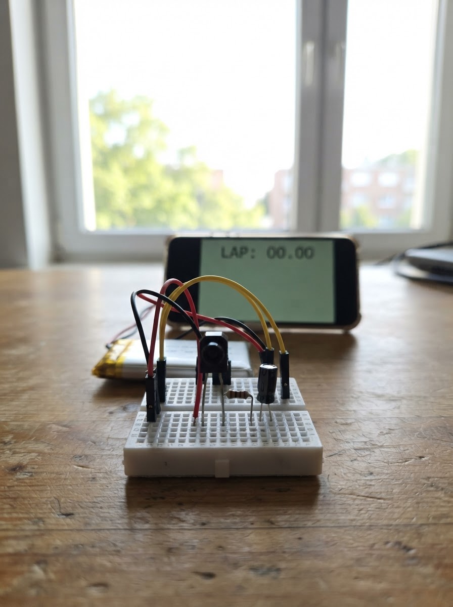
Build a lap timing system that tracks multiple racers using infrared detection. This standalone monitor uses an ESP32 microcontroller with an integrated display to capture IR signals from passing vehicles or objects, decode their unique signatures, and log lap times in real-time. The system can track up to 8 racers simultaneously, displaying elapsed time and lap counts on the built-in screen.
This guide provides a complete parts list, wiring diagram, and firmware to get the lap monitor running. Assembly takes just minutes—position the IR receiver at the finish line, connect power and signal lines to the ESP32, and upload the provided code. Once powered on, the display shows a live leaderboard that updates as each racer crosses the sensor.
Wiring diagram
Gather all the parts
Assemble it in 5 steps
1. Keep the screen built into the yellow display
Use the Cheap Yellow Display as the monitor body. Its large 2.8-inch screen is already wired inside the board, so do not add the separate 0.96-inch OLED from version 1.
- The built-in screen is landscape in this version, giving each car a larger, easier-to-read row.
- Do not connect anything to the display’s internal screen pins; they are already used inside the Cheap Yellow Display.
2. Place the infrared receiver at the finish line
Mount the TSOP38238 with its dark sensing face aimed upward where the underside of each RC car passes. Put the Cheap Yellow Display in a small box beside the track, then run three wires from the receiver to the display board.
- Start with the receiver 5 to 15 cm from the transponder path. A short black tube around its sensing face helps it ignore light from the sides.
- Keep the receiver out of direct sun and away from halogen lamps because strong infrared light can cause missed or false lap counts.
3. Add clean power for the receiver
Connect the 100 Ω resistor A leg to the Cheap Yellow Display 3V3 pin (power). Connect resistor B to the TSOP38238 VS pin (clean receiver power). Put the capacitor’s long positive lead on that same VS connection (power), and put its striped negative lead on a GND pin (ground).
- Keep the resistor and capacitor physically close to the receiver so they can reduce electrical noise.
- Make sure the capacitor’s striped negative lead goes to GND — reversing it can damage the capacitor.
4. Connect the receiver signal
Connect TSOP38238 GND to a Cheap Yellow Display GND pin (ground). Connect TSOP38238 OUT to GPIO35 (signal). GPIO35 is input-only, which is exactly what the receiver needs.
- Keep the OUT wire short and away from USB power cables or motor wiring to reduce noise.
- Use the board’s 3V3 pin for the receiver circuit, not 5V; this keeps the receiver output safe for the display board’s 3.3 V signal input.
5. Power and test the monitor
Check every connection with USB unplugged, then plug the Cheap Yellow Display into USB power. The built-in screen shows RC LAP MONITOR. Pass one active transponder under the receiver; its first detection creates a car row, and later passes at least three seconds apart add laps.
- Test one car first. The displayed four-digit car label is derived from its infrared pattern, so it stays consistent during a race.
- Unplug USB before moving wires. Do not enclose the receiver behind dark plastic that blocks infrared light.
Review all connections
1. Connections between "ir_supply_resistor_1" and "ESP32"
2. Connections between "ir_filter_capacitor_1" and "ESP32"
3. Connections between "ir_receiver_1" and "ESP32"
Deploy the firmware
#include <Arduino.h>
#include <Arduino_GFX_Library.h>


// Hoisted type definitions
struct Racer {
  uint32_t signature;
  uint32_t lastLapMs;
  uint32_t lastSeenMs;
  uint16_t laps;
  bool used;
};


// Forward declarations
void IRAM_ATTR onIrEdge();
uint32_t signatureForFrame(const uint16_t *durations, uint8_t count);
int findRacer(uint32_t signature);
void formatTime(uint32_t milliseconds, char *out, size_t size);
void drawClock();
void drawRow(uint8_t racerIndex);
void drawInitialScreen();
void processFrame();

constexpr uint8_t IR_OUT_PIN = 35;
constexpr uint8_t TFT_CS_PIN = 15;
constexpr uint8_t TFT_DC_PIN = 2;
constexpr uint8_t TFT_SCK_PIN = 14;
constexpr uint8_t TFT_MOSI_PIN = 13;
constexpr uint8_t TFT_BACKLIGHT_PIN = 21;
constexpr uint8_t MAX_EDGES = 96;
constexpr uint8_t MAX_CARS = 8;
constexpr uint32_t FRAME_GAP_US = 8000;
constexpr uint32_t MIN_LAP_MS = 3000;
constexpr uint16_t BACKGROUND = 0x0000;
constexpr uint16_t HEADER = 0x001F;
constexpr uint16_t TEXT = 0xFFFF;
constexpr uint16_t ACCENT = 0xFFE0;


Arduino_DataBus *bus = new Arduino_ESP32SPI(TFT_DC_PIN, TFT_CS_PIN, TFT_SCK_PIN, TFT_MOSI_PIN, GFX_NOT_DEFINED, HSPI);
Arduino_GFX *display = new Arduino_ILI9341(bus, GFX_NOT_DEFINED, 0, false);

volatile uint16_t edgeDurations[MAX_EDGES];
volatile uint8_t edgeCount = 0;
volatile uint32_t lastEdgeUs = 0;
volatile bool captureOverflow = false;
Racer racers[MAX_CARS] = {};
uint32_t raceStartedMs = 0;
uint32_t lastClockSecond = UINT32_MAX;
bool screenInitialized = false;

void IRAM_ATTR onIrEdge() {
  const uint32_t now = micros();
  const uint32_t duration = now - lastEdgeUs;
  lastEdgeUs = now;
  if (edgeCount < MAX_EDGES) {
    edgeDurations[edgeCount++] = duration > 65535UL ? 65535U : static_cast<uint16_t>(duration);
  } else {
    captureOverflow = true;
  }
}

uint32_t signatureForFrame(const uint16_t *durations, uint8_t count) {
  uint32_t hash = 2166136261UL;
  for (uint8_t i = 1; i < count; ++i) {
    hash ^= (durations[i] + 125U) / 250U;
    hash *= 16777619UL;
  }
  return hash == 0 ? 1 : hash;
}

int findRacer(uint32_t signature) {
  for (uint8_t i = 0; i < MAX_CARS; ++i) {
    if (racers[i].used && racers[i].signature == signature) return i;
  }
  for (uint8_t i = 0; i < MAX_CARS; ++i) {
    if (!racers[i].used) {
      racers[i] = {signature, 0, 0, 0, true};
      return i;
    }
  }
  return -1;
}

void formatTime(uint32_t milliseconds, char *out, size_t size) {
  const uint32_t seconds = milliseconds / 1000UL;
  snprintf(out, size, "%lu:%02lu.%lu", static_cast<unsigned long>(seconds / 60UL), static_cast<unsigned long>(seconds % 60UL), static_cast<unsigned long>((milliseconds % 1000UL) / 100UL));
}

void drawClock() {
  char timeText[12];
  formatTime(millis() - raceStartedMs, timeText, sizeof(timeText));
  display->fillRect(178, 7, 58, 18, HEADER);
  display->setTextColor(TEXT, HEADER);
  display->setTextSize(2);
  display->setCursor(178, 7);
  display->print(timeText);
}

void drawRow(uint8_t racerIndex) {
  const int16_t y = 48 + racerIndex * 32;
  display->fillRect(0, y, 240, 30, BACKGROUND);
  if (!racers[racerIndex].used) return;
  char lapText[12];
  display->setTextSize(2);
  display->setTextColor(ACCENT, BACKGROUND);
  display->setCursor(8, y + 6);
  display->printf("CAR %04lu", static_cast<unsigned long>(racers[racerIndex].signature % 10000UL));
  display->setTextColor(TEXT, BACKGROUND);
  display->setCursor(116, y + 6);
  display->printf("LAP %u", racers[racerIndex].laps);
  formatTime(racers[racerIndex].lastLapMs, lapText, sizeof(lapText));
  display->setCursor(184, y + 6);
  display->print(racers[racerIndex].lastLapMs == 0 ? "--:--.-" : lapText);
}

void drawInitialScreen() {
  display->fillScreen(BACKGROUND);
  display->fillRect(0, 0, 240, 34, HEADER);
  display->setTextColor(TEXT, HEADER);
  display->setTextSize(2);
  display->setCursor(8, 7);
  display->print("RC LAP MONITOR");
  display->drawFastHLine(0, 38, 240, TEXT);
  for (uint8_t i = 0; i < MAX_CARS; ++i) drawRow(i);
  display->setTextColor(TEXT, BACKGROUND);
  display->setTextSize(2);
  display->setCursor(28, 152);
  display->print("Waiting for transponders");
  screenInitialized = true;
}

void processFrame() {
  uint16_t localDurations[MAX_EDGES];
  uint8_t count;
  bool overflow;
  noInterrupts();
  count = edgeCount;
  overflow = captureOverflow;
  for (uint8_t i = 0; i < count; ++i) localDurations[i] = edgeDurations[i];
  edgeCount = 0;
  captureOverflow = false;
  interrupts();
  if (overflow || count < 12) return;

  const int racerIndex = findRacer(signatureForFrame(localDurations, count));
  if (racerIndex < 0) return;
  const uint32_t nowMs = millis();
  Racer &racer = racers[racerIndex];
  if (racer.lastSeenMs && nowMs - racer.lastSeenMs < MIN_LAP_MS) return;
  racer.lastLapMs = racer.lastSeenMs ? nowMs - racer.lastSeenMs : 0;
  racer.lastSeenMs = nowMs;
  racer.laps++;
  if (screenInitialized) {
    display->fillRect(28, 152, 210, 20, BACKGROUND);
    drawRow(racerIndex);
  }
}

void setup() {
  pinMode(TFT_BACKLIGHT_PIN, OUTPUT);
  digitalWrite(TFT_BACKLIGHT_PIN, HIGH);
  display->begin();
  display->setRotation(1);
  drawInitialScreen();
  pinMode(IR_OUT_PIN, INPUT);
  lastEdgeUs = micros();
  attachInterrupt(digitalPinToInterrupt(IR_OUT_PIN), onIrEdge, CHANGE);
  raceStartedMs = millis();
}

void loop() {
  if (edgeCount && micros() - lastEdgeUs > FRAME_GAP_US) processFrame();
  const uint32_t second = (millis() - raceStartedMs) / 1000UL;
  if (second != lastClockSecond) {
    drawClock();
    lastClockSecond = second;
  }
}
Remix this project
Make it yours in one click
Open a full copy of this project in your own Schematik workspace — diagram, code, parts, and assembly steps included. Swap the sensor, add features, or redesign the whole thing with AI. The author's original stays untouched.