Community project
Suprise Me
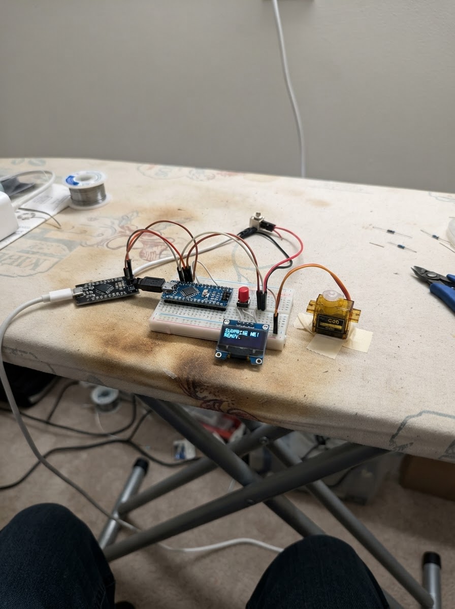
Surprise Me is a phone lockbox timer that uses an ESP32 to control a servo-driven mechanical latch, keeping devices locked away for a set duration. The project combines an SSD1306 OLED display for countdown feedback, a push button to start sessions, and a SG90 servo motor powered independently to ensure reliable locking and unlocking.
This guide provides a complete wiring diagram, parts list, and firmware to build a non-destructive lockbox that secures a phone or small item for focused time intervals. Builders will learn how to interface the ESP32 with display and servo peripherals, implement debounced button input, and test the mechanical latch before deployment.
Wiring diagram

Gather all the parts
Assemble it in 4 steps
1. Prepare a non-destructive lockbox
Use a small box with a lid and make a simple latch from a rigid tab, printed part, or light metal strip. Mount servo_lock_1 so its horn can rotate between a clear open position and a position that blocks the lid. Do not make a permanently trapped enclosure: the lid must still have a safe manual way to open.
- Before attaching the horn screw, power the ESP32 and confirm the servo is at its open position.
- Adjust the horn and latch geometry so LOCK_ANGLE blocks the lid without forcing it.
- This is a voluntary focus aid, not a security safe.
- Keep the phone reachable in an emergency; the locking force must be light enough not to damage the phone, box, cable, or fingers.
2. Wire the timer controls and display
Connect oled_1 VCC to ESP32 3V3, GND to ESP32 GND, SDA to GPIO21, and SCL to GPIO22. Connect one terminal of button_1 to GPIO27 and its other terminal to GND.
- Use the OLED pins printed on its board; many modules use I2C address 0x3C.
- The button uses the ESP32 internal pull-up, so no separate resistor is needed.
- Do not connect the OLED VCC to 5 V.
3. Wire the servo with its independent supply
Connect servo_lock_1 SIGNAL to ESP32 GPIO26. Connect servo_supply_1 +5V to manual_release_1 PIN1, then manual_release_1 PIN2 to servo_lock_1 VCC. Connect servo_lock_1 GND to servo_supply_1 GND. Also connect servo_supply_1 GND to an ESP32 GND pin so the signal has a shared reference.
- Use a regulated 5 V supply rated for at least 2 A for the servo.
- Put the manual release switch where it remains accessible without opening the box.
- Never power the servo from the ESP32 3.3 V pin.
- The manual release removes servo power only; test that you can mechanically open the box before placing a phone inside.
4. Test the latch before using a phone
Power the ESP32 from USB and power the servo_supply_1 separately. With the box empty, press button_1: the display begins at 25:00 and the servo should rotate to block the lid. Button presses are intentionally ignored during the countdown. At zero, the servo returns to the open position.
- If the horn moves the wrong way or the latch does not align, reposition the horn mechanically first; the supplied firmware uses 15 degrees open and 105 degrees locked.
- Only after repeated empty-box tests should you place a phone inside.
- Do not rely on this project to restrict access during an emergency.
- Turn off the accessible manual-release switch if the servo stalls, chatters, or the mechanism binds.
Review all connections
1. Connections between "oled_1" and "ESP32"
2. Connections between "button_1" and "ESP32"
3. Connections between "servo_lock_1" and "ESP32"
4. Connections between "servo_supply_1" and "ESP32"
Deploy the firmware
#include <Arduino.h>
#include <Wire.h>
#include <Adafruit_GFX.h>
#include <Adafruit_SSD1306.h>
#include <ESP32Servo.h>


// Hoisted type definitions
enum TimerState { READY, LOCKED_RUNNING, FINISHED };


// Forward declarations
void moveLock(bool lockBox);
void drawScreen();
void startSession();
void handleButtonPress();

constexpr int OLED_SDA = 21;
constexpr int OLED_SCL = 22;
constexpr int BUTTON_PIN = 27;
constexpr int SERVO_PIN = 26;
constexpr uint32_t SESSION_SECONDS = 25UL * 60UL;
constexpr uint32_t DEBOUNCE_MS = 35;
constexpr int UNLOCK_ANGLE = 15;
constexpr int LOCK_ANGLE = 105;


Adafruit_SSD1306 display(128, 64, &Wire, -1);
Servo lockServo;
TimerState timerState = READY;
uint32_t remainingSeconds = SESSION_SECONDS;
uint32_t lastTickMs = 0;
bool lastButtonReading = HIGH;
bool stableButtonState = HIGH;
uint32_t lastDebounceMs = 0;

void moveLock(bool lockBox) {
  lockServo.write(lockBox ? LOCK_ANGLE : UNLOCK_ANGLE);
}

void drawScreen() {
  display.clearDisplay();
  display.setTextColor(SSD1306_WHITE);
  display.setTextSize(1);
  display.setCursor(25, 1);
  display.print("PHONE LOCKBOX");
  display.drawLine(0, 12, 127, 12, SSD1306_WHITE);

  const uint32_t minutes = remainingSeconds / 60;
  const uint32_t seconds = remainingSeconds % 60;
  char timeText[6];
  snprintf(timeText, sizeof(timeText), "%02lu:%02lu", static_cast<unsigned long>(minutes), static_cast<unsigned long>(seconds));
  display.setTextSize(3);
  display.setCursor(18, 22);
  display.print(timeText);

  display.setTextSize(1);
  display.setCursor(5, 54);
  if (timerState == READY) display.print("Place phone in; press to lock");
  else if (timerState == LOCKED_RUNNING) display.print("Locked until timer ends");
  else display.print("Unlocked! Press for new session");
  display.display();
}

void startSession() {
  remainingSeconds = SESSION_SECONDS;
  moveLock(true);
  delay(350);
  timerState = LOCKED_RUNNING;
  lastTickMs = millis();
  drawScreen();
}

void handleButtonPress() {
  if (timerState == READY || timerState == FINISHED) startSession();
}

void setup() {
  pinMode(BUTTON_PIN, INPUT_PULLUP);
  Wire.begin(OLED_SDA, OLED_SCL);
  lockServo.setPeriodHertz(50);
  lockServo.attach(SERVO_PIN, 500, 2400);
  moveLock(false);
  if (!display.begin(SSD1306_SWITCHCAPVCC, 0x3C)) while (true) delay(1000);
  drawScreen();
}

void loop() {
  const uint32_t now = millis();
  const bool reading = digitalRead(BUTTON_PIN);
  if (reading != lastButtonReading) lastDebounceMs = now;
  if (now - lastDebounceMs >= DEBOUNCE_MS && reading != stableButtonState) {
    stableButtonState = reading;
    if (stableButtonState == LOW) handleButtonPress();
  }
  lastButtonReading = reading;

  if (timerState == LOCKED_RUNNING && now - lastTickMs >= 1000) {
    const uint32_t elapsedSeconds = (now - lastTickMs) / 1000;
    lastTickMs += elapsedSeconds * 1000;
    if (elapsedSeconds >= remainingSeconds) {
      remainingSeconds = 0;
      timerState = FINISHED;
      moveLock(false);
    } else {
      remainingSeconds -= elapsedSeconds;
    }
    drawScreen();
  }
}
Remix this project
Make it yours in one click
Open a full copy of this project in your own Schematik workspace — diagram, code, parts, and assembly steps included. Swap the sensor, add features, or redesign the whole thing with AI. The author's original stays untouched.