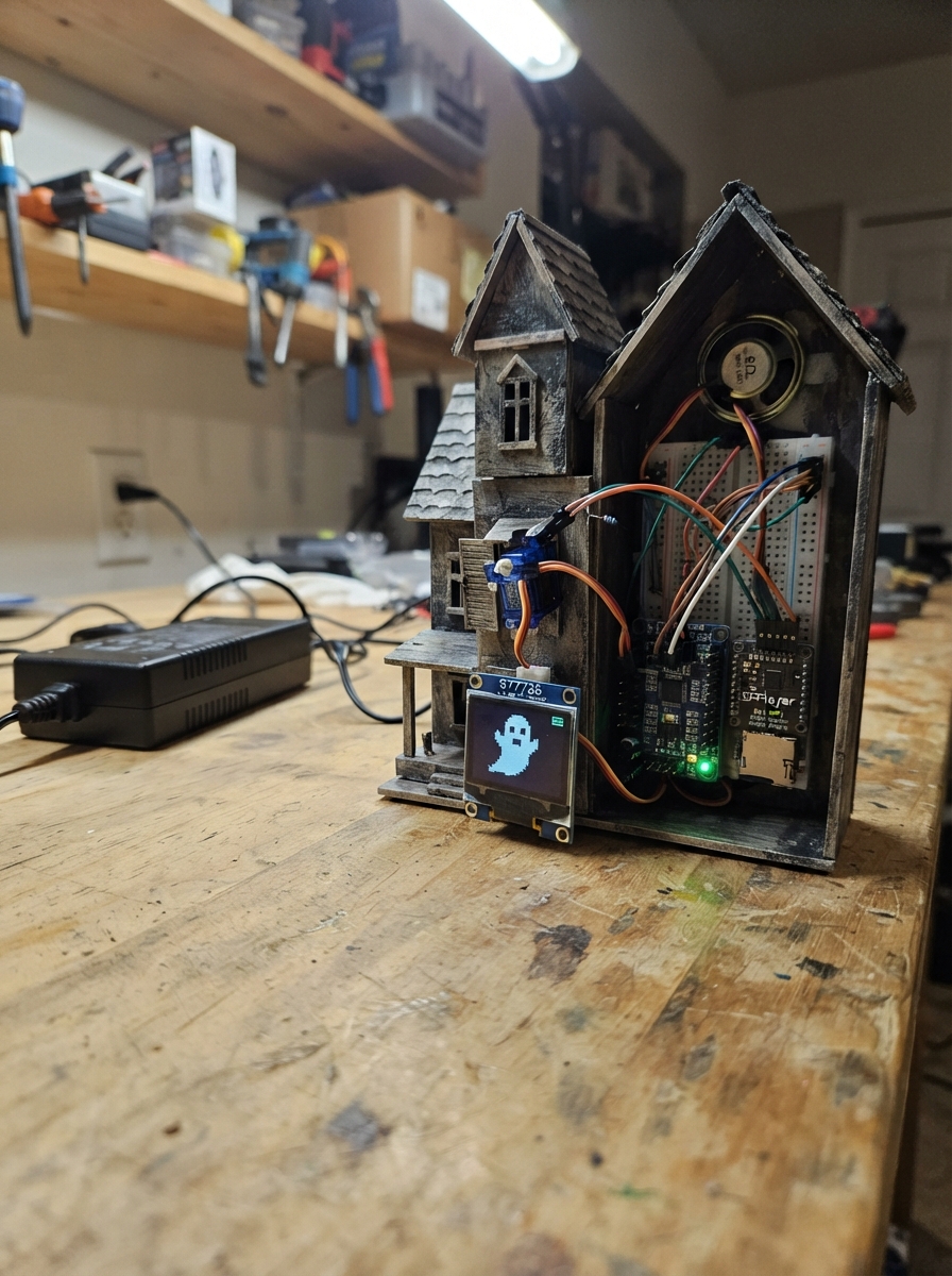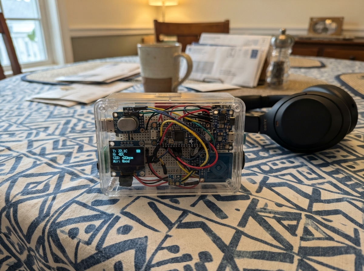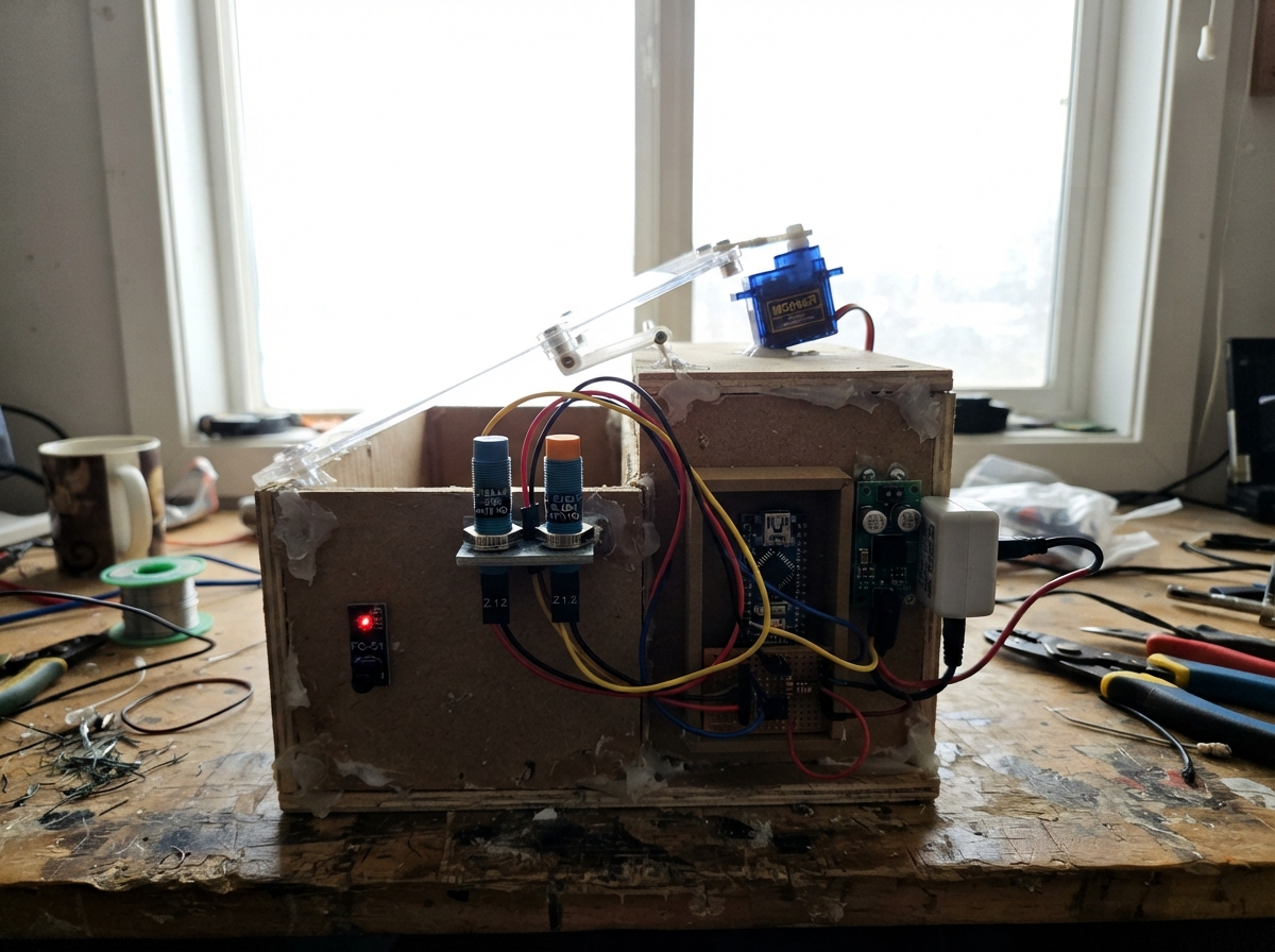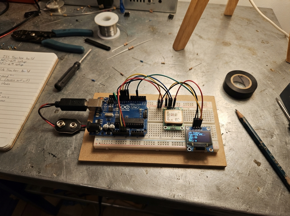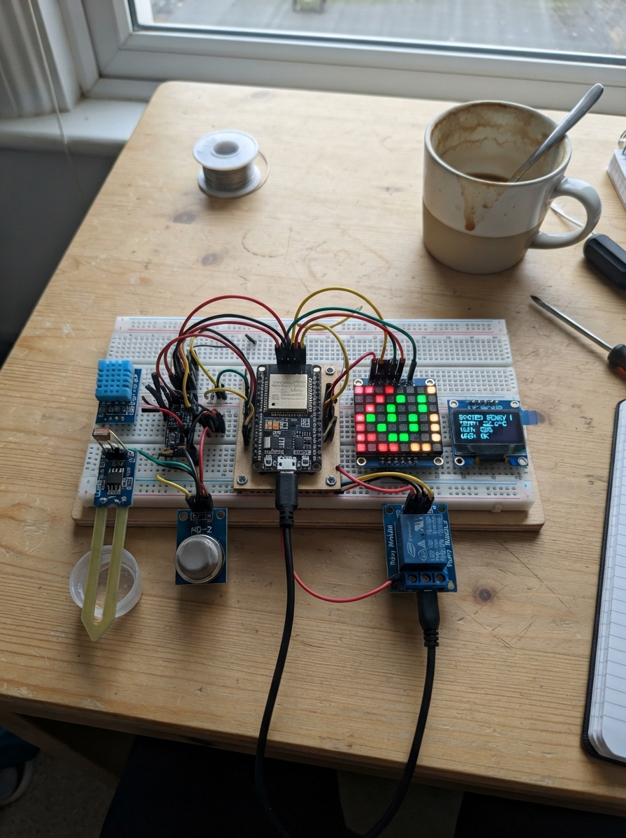
This ESP32 control project monitors environmental conditions and triggers alerts using a comprehensive sensor array including temperature, light, water level, and gas detection. The system displays real-time data on an OLED screen and a 64-pixel RGB matrix, with audio-visual alerts via a buzzer and relay-controlled pump activation.
The guide provides a complete parts list, wiring diagram with GPIO assignments, and step-by-step assembly instructions. Firmware with Bluetooth Low Energy support and configurable thresholds is included, allowing makers to customize sensor sensitivity and integrate the system into their own applications.
Wiring diagram
Gather all the parts
Assemble it in 6 steps
1. Keep power disconnected while wiring
Place the ESP32 DevKit, sensors, OLED, matrix, relay, and buzzer where their printed pin labels can be read. Leave the USB cable and the two-cell battery disconnected until every wire has been checked.
- Use one common ground rail: every GND connection listed below joins the ESP32 GND pin.
- GPIO36 is not used for the air-pump control; GPIO25 is the relay-control wire.
- Do not connect the 7.4–8.4 V two-cell battery directly to an ESP32 3V3 or 5V pin; that can permanently damage the board.
2. Wire the temperature, light, and water sensors
Connect temperature_sensor VCC → 3V3 (power), temperature_sensor GND → GND (ground), and temperature_sensor DATA → GPIO14 (temperature signal). Connect light_sensor VCC → 3V3 (power), light_sensor GND → GND (ground), and light_sensor AO → GPIO15 (light signal). Connect water_sensor + → 3V3 (power), water_sensor - → GND (ground), and water_sensor S → GPIO39 (water signal).
- Use the AO pin, not the DO pin, on the light module because the program reads the amount of light.
- Powering the light and water modules from 3V3 keeps their signal wires within the ESP32's safe voltage range.
- GPIO15 affects ESP32 startup. Do not let the light module or loose wires force this pin high or low while the ESP32 is being reset.
3. Wire both smoke sensors and the battery monitor
Connect smoke_sensor_input VCC → 5V (heater power), smoke_sensor_input GND → GND (ground), and smoke_sensor_input AO → GPIO32 (incoming-smoke signal). Connect smoke_sensor_output VCC → 5V (heater power), smoke_sensor_output GND → GND (ground), and smoke_sensor_output AO → GPIO33 (outgoing-smoke signal). Connect battery_pack BAT+ → battery_divider VIN (battery-voltage input), battery_pack BAT- → GND (ground), battery_divider GND → GND (ground), and battery_divider OUT → GPIO35 (scaled battery-voltage signal).
- The MQ-2 sensors need about 20–30 seconds to warm up before their readings settle.
- The code assumes the battery divider is 20 kΩ from BAT+ to OUT and 10 kΩ from OUT to GND, which makes the voltage at GPIO35 one-third of the battery voltage.
- The MQ-2 AO pins must already be reduced to 3.3 V or less before reaching GPIO32 and GPIO33. A 5 V analogue signal can damage the ESP32.
- Make sure the battery-divider output cannot exceed 3.3 V at a fully charged battery voltage of 8.4 V.
4. Wire the OLED and matrix display
Connect oled VCC → 3V3 (power), oled GND → GND (ground), oled SDA → GPIO21 (data), and oled SCL → GPIO22 (clock). Connect matrix_display VCC → 5V (matrix power), matrix_display GND → GND (shared ground), and matrix_display DIN → GPIO4 (matrix data).
- Read the labels printed on the OLED board because similar OLED boards may arrange the four header pins in a different order.
- The program keeps the matrix dim, so it is used as a simple dark-condition indicator rather than a high-current lamp.
- Make sure VCC and GND are not swapped on the OLED or matrix; swapped power can damage them.
- The 5 V matrix needs a power supply that can provide its current. Its ground must remain connected to ESP32 GND.
5. Wire the air-pump relay and alert buzzer
Connect air_pump_relay VCC → 5V (relay power), air_pump_relay GND → GND (ground), and air_pump_relay IN → GPIO25 (air-pump control). Connect buzzer SIG → GPIO27 (alert tone), and buzzer GND → GND (ground). Use the relay's existing COM and NO screw terminals in series with the existing air-pump supply lead so the relay can switch the pump without passing pump current through the ESP32.
- On the common relay module, the pump stays off at startup because the program treats a low relay input as active.
- The buzzer sounds for water, smoke, or over-temperature conditions.
- Never connect an air pump directly to GPIO25; the pin only sends a small control signal and cannot supply pump power.
- Keep the high-current pump wires in the relay screw terminals, not on the ESP32 breadboard pins.
6. Check the system before switching it on
Check that every module ground reaches ESP32 GND, that the battery only reaches GPIO35 through battery_divider, and that the relay input is on GPIO25. Then connect the ESP32 by USB, allow both smoke sensors to warm up, and verify that the OLED starts showing the BIOTECH PRANVAYU pages.
- In nRF Connect, scan for the exact device name #BIOTECH PRANVAYU 0001 and open its readable/notifiable status characteristic.
- If the displayed battery voltage differs from a meter, adjust BATTERY_CALIBRATION in the program after measuring the real pack voltage.
- Do not test a water-leak alarm by pouring water onto the ESP32 or breadboard; wet only the sensing end of the water sensor.
Review all connections
1. Connections between "temperature_sensor" and "ESP32"
2. Connections between "light_sensor" and "ESP32"
3. Connections between "water_sensor" and "ESP32"
4. Connections between "smoke_sensor_input" and "ESP32"
5. Connections between "smoke_sensor_output" and "ESP32"
6. Connections between "battery_pack" and "ESP32"
7. Connections between "battery_divider" and "ESP32"
8. Connections between "oled" and "ESP32"
9. Connections between "matrix_display" and "ESP32"
10. Connections between "air_pump_relay" and "ESP32"
11. Connections between "buzzer" and "ESP32"
Deploy the firmware
#include <Arduino.h>
#include <Wire.h>
#include <DHT.h>
#include <Adafruit_GFX.h>
#include <Adafruit_SSD1306.h>
#include <Adafruit_NeoPixel.h>
#include <BLEDevice.h>
#include <BLEServer.h>
#include <BLEUtils.h>
#include <BLE2902.h>

// Required GPIO assignments
constexpr uint8_t DHT_PIN = 14;
constexpr uint8_t LDR_PIN = 15;
constexpr uint8_t WATER_PIN = 39;
constexpr uint8_t SMOKE_IN_PIN = 32;
constexpr uint8_t SMOKE_OUT_PIN = 33;
constexpr uint8_t BATTERY_PIN = 35;
constexpr uint8_t PUMP_RELAY_PIN = 25;
constexpr uint8_t BUZZER_PIN = 27;
constexpr uint8_t MATRIX_PIN = 4;
constexpr uint8_t OLED_SDA_PIN = 21;
constexpr uint8_t OLED_SCL_PIN = 22;

// Adjustable application thresholds. Change only these values when tuning the system.
constexpr float TEMPERATURE_LIMIT_C = 35.0f;
constexpr int LIGHT_DARK_THRESHOLD = 1800;
constexpr int WATER_DETECTED_THRESHOLD = 600;
constexpr int SMOKE_IN_ALERT_THRESHOLD = 1800;
constexpr int SMOKE_OUT_ALERT_THRESHOLD = 1800;

// Battery-divider calibration: this assumes the existing divider reduces battery voltage by 3:1.
// Example: 20 kOhm from BAT+ to OUT and 10 kOhm from OUT to GND.
constexpr float BATTERY_DIVIDER_RATIO = 3.0f;
constexpr float BATTERY_CALIBRATION = 1.000f;
constexpr float BATTERY_EMPTY_V = 6.00f;
constexpr float BATTERY_FULL_V = 8.40f;

constexpr bool RELAY_ACTIVE_LOW = true;
constexpr uint8_t DHT_TYPE = DHT11;
constexpr uint8_t BUZZER_CHANNEL = 0;
constexpr uint32_t SENSOR_INTERVAL_MS = 1000;
constexpr uint32_t DISPLAY_PAGE_INTERVAL_MS = 3000;
constexpr uint32_t BLE_UPDATE_INTERVAL_MS = 1000;
constexpr uint8_t MATRIX_BRIGHTNESS = 12; // Keeps the 8x8 matrix current low.

const char *DEVICE_NAME = "#BIOTECH PRANVAYU 0001";
const char *SERVICE_UUID = "7a8353f1-5e19-4e6b-80d8-4c6300020001";
const char *STATUS_UUID  = "7a8353f1-5e19-4e6b-80d8-4c6300020002";

DHT dht(DHT_PIN, DHT_TYPE);
Adafruit_SSD1306 display(128, 64, &Wire, -1);
Adafruit_NeoPixel matrix(64, MATRIX_PIN, NEO_GRB + NEO_KHZ800);
BLECharacteristic *statusCharacteristic = nullptr;

struct SystemState {
  float temperatureC = NAN;
  int lightRaw = 0;
  int waterRaw = 0;
  int smokeInRaw = 0;
  int smokeOutRaw = 0;
  float batteryV = 0.0f;
  int batteryPercent = 0;
  bool temperatureValid = false;
  bool waterDetected = false;
  bool dark = false;
  bool smokeInAlert = false;
  bool smokeOutAlert = false;
  bool pumpOn = false;
  bool buzzerOn = false;
  bool matrixOn = false;
  bool bleConnected = false;
};

SystemState state;
uint32_t lastSensorMs = 0;
uint32_t lastDisplayMs = 0;
uint32_t lastBleMs = 0;
uint8_t displayPage = 0;

class ServerCallbacks : public BLEServerCallbacks {
  void onConnect(BLEServer *) override { state.bleConnected = true; }
  void onDisconnect(BLEServer *server) override {
    state.bleConnected = false;
    delay(100);
    server->startAdvertising();
  }
};

void setRelay(bool on) {
  state.pumpOn = on;
  bool level = RELAY_ACTIVE_LOW ? !on : on;
  digitalWrite(PUMP_RELAY_PIN, level ? HIGH : LOW);
}

void setBuzzer(bool on) {
  state.buzzerOn = on;
  if (on) {
    ledcWriteTone(BUZZER_PIN, 2400);
  } else {
    ledcWriteTone(BUZZER_PIN, 0);
  }
}

void setMatrix(bool on) {
  state.matrixOn = on;
  matrix.clear();
  if (on) {
    for (uint16_t i = 0; i < matrix.numPixels(); ++i) {
      matrix.setPixelColor(i, matrix.Color(0, 35, 0));
    }
  }
  matrix.show();
}

float readBatteryVoltage() {
  uint32_t millivolts = analogReadMilliVolts(BATTERY_PIN);
  return (millivolts / 1000.0f) * BATTERY_DIVIDER_RATIO * BATTERY_CALIBRATION;
}

int batteryPercent(float voltage) {
  float percent = (voltage - BATTERY_EMPTY_V) * 100.0f / (BATTERY_FULL_V - BATTERY_EMPTY_V);
  return constrain((int)lroundf(percent), 0, 100);
}

void readSensorsAndControl() {
  float reading = dht.readTemperature();
  if (!isnan(reading)) {
    state.temperatureC = reading;
    state.temperatureValid = true;
  } else {
    state.temperatureValid = false;
  }

  state.lightRaw = analogRead(LDR_PIN);
  state.waterRaw = analogRead(WATER_PIN);
  state.smokeInRaw = analogRead(SMOKE_IN_PIN);
  state.smokeOutRaw = analogRead(SMOKE_OUT_PIN);
  state.batteryV = readBatteryVoltage();
  state.batteryPercent = batteryPercent(state.batteryV);

  state.dark = state.lightRaw < LIGHT_DARK_THRESHOLD;
  state.waterDetected = state.waterRaw >= WATER_DETECTED_THRESHOLD;
  state.smokeInAlert = state.smokeInRaw >= SMOKE_IN_ALERT_THRESHOLD;
  state.smokeOutAlert = state.smokeOutRaw >= SMOKE_OUT_ALERT_THRESHOLD;

  bool overTemperature = state.temperatureValid && state.temperatureC >= TEMPERATURE_LIMIT_C;
  bool critical = state.waterDetected || state.smokeInAlert || state.smokeOutAlert || overTemperature;
  setRelay(overTemperature || state.smokeInAlert || state.smokeOutAlert);
  setBuzzer(critical);
  setMatrix(state.dark);
}

void printHeader(const char *title) {
  display.setTextSize(1);
  display.setTextColor(SSD1306_WHITE);
  display.setCursor(0, 0);
  display.print("BIOTECH PRANVAYU");
  display.setCursor(0, 10);
  display.print(title);
}

void drawDisplay() {
  display.clearDisplay();
  if (displayPage == 0) {
    printHeader("ENVIRONMENT");
    display.setCursor(0, 23);
    if (state.temperatureValid) {
      display.printf("Temp: %.1f C", state.temperatureC);
    } else {
      display.print("Temp: SENSOR ERROR");
    }
    display.setCursor(0, 35);
    display.printf("Light: %d %s", state.lightRaw, state.dark ? "DARK" : "BRIGHT");
    display.setCursor(0, 47);
    display.printf("Water: %s", state.waterDetected ? "DETECTED" : "NORMAL");
  } else if (displayPage == 1) {
    printHeader("SMOKE / BATTERY");
    display.setCursor(0, 23);
    display.printf("Smoke IN : %d", state.smokeInRaw);
    display.setCursor(0, 35);
    display.printf("Smoke OUT: %d", state.smokeOutRaw);
    display.setCursor(0, 47);
    display.printf("Battery: %.2fV %d%%", state.batteryV, state.batteryPercent);
  } else {
    printHeader("SYSTEM STATUS");
    display.setCursor(0, 23);
    display.printf("Air pump: %s", state.pumpOn ? "ON" : "OFF");
    display.setCursor(0, 35);
    display.printf("Buzzer: %s", state.buzzerOn ? "ALERT" : "OFF");
    display.setCursor(0, 47);
    display.printf("Matrix:%s BLE:%s", state.matrixOn ? "ON" : "OFF", state.bleConnected ? "ON" : "WAIT");
  }
  display.display();
}

String makeStatusJson() {
  String payload = "{";
  payload += "\"project\":\"BIOTECH PRANVAYU\",";
  payload += "\"temperature_c\":" + String(state.temperatureValid ? state.temperatureC : -127.0f, 1) + ",";
  payload += "\"light_raw\":" + String(state.lightRaw) + ",";
  payload += "\"light_status\":\"" + String(state.dark ? "DARK" : "BRIGHT") + "\",";
  payload += "\"water_status\":\"" + String(state.waterDetected ? "WATER DETECTED" : "NORMAL") + "\",";
  payload += "\"smoke_input\":" + String(state.smokeInRaw) + ",";
  payload += "\"smoke_output\":" + String(state.smokeOutRaw) + ",";
  payload += "\"battery_percent\":" + String(state.batteryPercent) + ",";
  payload += "\"battery_voltage\":" + String(state.batteryV, 2) + ",";
  payload += "\"air_pump\":\"" + String(state.pumpOn ? "ON" : "OFF") + "\",";
  payload += "\"buzzer\":\"" + String(state.buzzerOn ? "ON" : "OFF") + "\",";
  payload += "\"matrix\":\"" + String(state.matrixOn ? "ON" : "OFF") + "\",";
  payload += "\"ble_connected\":" + String(state.bleConnected ? "true" : "false");
  payload += "}";
  return payload;
}

void updateBle() {
  if (statusCharacteristic == nullptr) return;
  String payload = makeStatusJson();
  statusCharacteristic->setValue(payload.c_str());
  if (state.bleConnected) statusCharacteristic->notify();
}

void setupBle() {
  BLEDevice::init(DEVICE_NAME);
  BLEServer *server = BLEDevice::createServer();
  server->setCallbacks(new ServerCallbacks());
  BLEService *service = server->createService(SERVICE_UUID);
  statusCharacteristic = service->createCharacteristic(
      STATUS_UUID, BLECharacteristic::PROPERTY_READ | BLECharacteristic::PROPERTY_NOTIFY);
  statusCharacteristic->addDescriptor(new BLE2902());
  statusCharacteristic->setValue("Starting");
  service->start();
  BLEAdvertising *advertising = BLEDevice::getAdvertising();
  advertising->addServiceUUID(SERVICE_UUID);
  advertising->setScanResponse(true);
  BLEDevice::startAdvertising();
}

void setup() {
  pinMode(PUMP_RELAY_PIN, OUTPUT);
  pinMode(BUZZER_PIN, OUTPUT);
  setRelay(false);
  ledcAttach(BUZZER_PIN, 2000, 8);
  setBuzzer(false);

  analogReadResolution(12);
  analogSetPinAttenuation(LDR_PIN, ADC_11db);
  analogSetPinAttenuation(WATER_PIN, ADC_11db);
  analogSetPinAttenuation(SMOKE_IN_PIN, ADC_11db);
  analogSetPinAttenuation(SMOKE_OUT_PIN, ADC_11db);
  analogSetPinAttenuation(BATTERY_PIN, ADC_11db);

  dht.begin();
  matrix.begin();
  matrix.setBrightness(MATRIX_BRIGHTNESS);
  setMatrix(false);

  Wire.begin(OLED_SDA_PIN, OLED_SCL_PIN);
  if (display.begin(SSD1306_SWITCHCAPVCC, 0x3C)) {
    display.clearDisplay();
    display.setTextColor(SSD1306_WHITE);
    display.setCursor(0, 0);
    display.println("BIOTECH PRANVAYU");
    display.println("Starting safely...");
    display.display();
  }
  setupBle();
}

void loop() {
  uint32_t now = millis();
  if (now - lastSensorMs >= SENSOR_INTERVAL_MS) {
    lastSensorMs = now;
    readSensorsAndControl();
  }
  if (now - lastDisplayMs >= DISPLAY_PAGE_INTERVAL_MS) {
    lastDisplayMs = now;
    displayPage = (displayPage + 1) % 3;
    drawDisplay();
  }
  if (now - lastBleMs >= BLE_UPDATE_INTERVAL_MS) {
    lastBleMs = now;
    updateBle();
  }
  delay(1);
}
Remix this project
Make it yours in one click
Open a full copy of this project in your own Schematik workspace, diagram, code, parts, and assembly steps included. Swap the sensor, add features, or redesign the whole thing with AI. The author's original stays untouched.