Community project
Temperature-Controlled Fan Hub
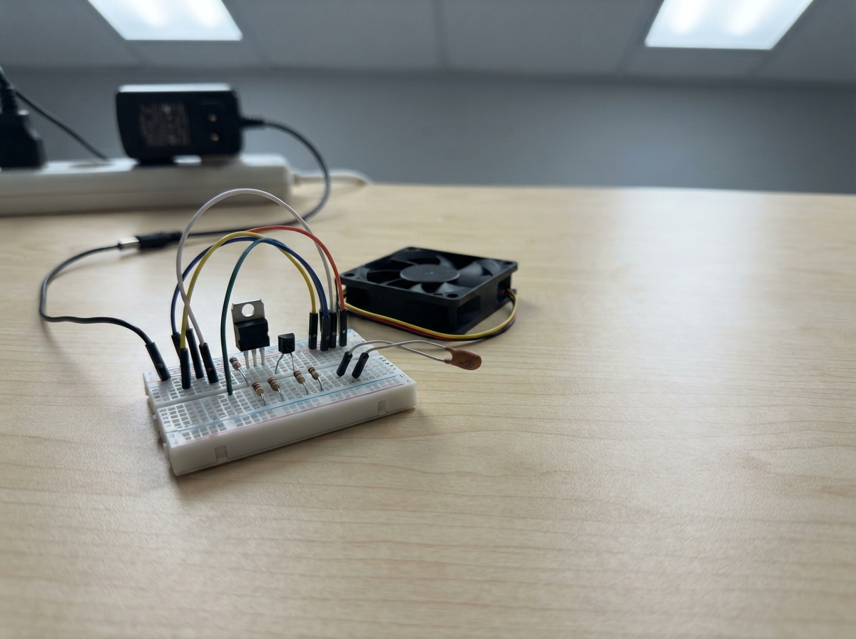
This temperature-controlled fan hub uses an ESP32-S3 to monitor thermal conditions and automatically adjust fan speeds based on real-time temperature readings. The system reads analog voltage from NTC thermistors, converts those readings to temperature values, and drives up to three 12 V PC fans via PWM-controlled transistor switches. A 5 V linear regulator powers the ESP32 from the same 12 V supply that feeds the fans, keeping the entire system on a single power input.
This guide provides a complete wiring diagram, full parts list with sourcing guidance, ESPHome firmware ready to customize, and step-by-step assembly instructions. Builders will learn how to condition analog sensor signals, implement thermal control logic, and safely switch higher-voltage loads from a microcontroller. The project is suitable for cooling enclosures, server racks, or any application requiring temperature-responsive fan management.
Wiring diagram

Gather all the parts
Assemble it in 7 steps
1. Place the 5 V regulator parts
With the 12 V supply unplugged, place the 7805 with its labelled face toward you. For the usual TO-220 7805 package, the left pin is IN, middle pin is GND, and right pin is OUT; check the printing or datasheet for your exact part before connecting it. Bolt regulator_heatsink to regulator_7805’s metal tab so it can release heat.
- Keep the regulator and its heatsink clear of wires and plastic.
- The 7805 must be a positive 7805/LM7805, not the negative 7905 originally shown.
- Do not power the circuit if the regulator pins are uncertain — swapping IN and OUT can damage the regulator and ESP32.
2. Add the regulator capacitors
Connect c1_input’s positive lead to the regulator IN pin and its negative striped lead to GND (input smoothing). Connect c2_output across the regulator output: one lead to OUT and the other to GND (output stability). Keep both capacitors physically close to the regulator pins.
- The 10 µF capacitor has polarity: its stripe marks the negative lead.
- The 100 nF ceramic capacitor has no polarity.
- Putting the 10 µF capacitor in backwards can make it overheat or burst.
3. Connect the shared 12 V supply
Connect the 12 V supply positive output to regulator_7805 IN and to the 12V wire on fan_1, fan_2, and fan_3 (power). Connect the supply negative output to the shared GND line (ground). This one supply feeds the fans directly and feeds the regulator separately.
- Use a 12 V supply rated for at least the three fans’ combined start-up current plus 0.5 A for the ESP32 regulator.
- Use thicker wire for the fan 12 V and GND connections than for the signal wires.
- Never connect the 12 V positive wire to an ESP32 pin, including 5V, 3V3, or any GPIO — this can permanently damage the board.
4. Power the ESP32 from the regulator
Connect regulator_7805 OUT to the ESP32-S3 Zero 5V/VIN pin (power). Connect regulator_7805 GND to an ESP32 GND pin (ground). The fan-supply negative, all fan grounds, transistor emitters, and ESP32 GND must be one shared ground connection.
- Measure between OUT and GND with a multimeter before attaching the ESP32; it should read close to +5 V.
- The 7805 heatsink may become warm in normal use.
- Do not connect the regulator OUT wire to the ESP32 3V3 pin — 5 V on that pin can permanently damage the board.
5. Build the five temperature probe junctions
For each probe, connect one NTC lead to ESP32 3V3 (power). Connect its other lead to its matching 10 kΩ resistor and the assigned GPIO (signal); connect the resistor’s other lead to GND (ground). Use GPIO1 for ntc_1, GPIO2 for ntc_2, GPIO3 for ntc_3, GPIO4 for ntc_4, and GPIO5 for ntc_5.
- The NTC probe leads have no polarity.
- Keep each probe’s signal junction away from the 12 V wiring.
- Do not connect an NTC signal junction to 12 V — ESP32 inputs accept only low-voltage signals.
6. Add the three fan control connections
For each fan, connect GPIO6 through base_r1 to pwm_q1 base, GPIO7 through base_r2 to pwm_q2 base, and GPIO8 through base_r3 to pwm_q3 base (control signals). Connect every transistor emitter to GND and each collector to its fan’s PWM wire. Connect fan_1 TACH to GPIO14 and tach_pullup_r1 to 3V3; fan_2 TACH to GPIO15 and tach_pullup_r2 to 3V3; and fan_3 TACH to GPIO17 and tach_pullup_r3 to 3V3 (speed signals).
- PWM is commonly the blue fan wire and TACH commonly green, but confirm with the fan’s label or datasheet.
- The onboard RGB status LED remains on GPIO16; do not connect a fan wire to GPIO16.
- Do not connect a fan PWM or TACH wire straight to the ESP32; the transistor and 3.3 V pull-up parts protect the ESP32 from higher fan signal voltages.
7. Inspect and power safely
Before switching on, verify that only fan wires and regulator IN receive +12 V, while regulator OUT alone goes to the ESP32 5V/VIN pin. Confirm every ground wire is joined. Turn on the 12 V supply, check the regulator output remains near 5 V, then power the firmware from the same board connection only after this check.
- If the 7805 becomes too hot to touch briefly, switch off immediately and use a larger heatsink or a 5 V buck converter.
- Use Schematik’s Deploy button to flash the firmware after the wiring is complete.
- Disconnect power immediately if a wire heats up, you smell hot plastic, or the regulator output is not close to 5 V.
Review all connections
1. Connections between "ntc_1" and "ESP32"
2. Connections between "ntc_ref_r1" and "ESP32"
3. Connections between "ntc_2" and "ESP32"
4. Connections between "ntc_ref_r2" and "ESP32"
5. Connections between "ntc_3" and "ESP32"
6. Connections between "ntc_ref_r3" and "ESP32"
7. Connections between "ntc_4" and "ESP32"
8. Connections between "ntc_ref_r4" and "ESP32"
9. Connections between "ntc_5" and "ESP32"
10. Connections between "ntc_ref_r5" and "ESP32"
11. Connections between "base_r1" and "ESP32"
12. Connections between "pwm_q1" and "ESP32"
13. Connections between "base_r2" and "ESP32"
14. Connections between "pwm_q2" and "ESP32"
15. Connections between "base_r3" and "ESP32"
16. Connections between "pwm_q3" and "ESP32"
17. Connections between "fan_supply" and "ESP32"
18. Connections between "fan_1" and "ESP32"
19. Connections between "tach_pullup_r1" and "ESP32"
20. Connections between "fan_2" and "ESP32"
21. Connections between "tach_pullup_r2" and "ESP32"
22. Connections between "tach_pullup_r3" and "ESP32"
23. Connections between "fan_3" and "ESP32"
24. Connections between "regulator_7805" and "ESP32"
25. Connections between "c1_input" and "ESP32"
26. Connections between "c2_output" and "ESP32"
Deploy the firmware
# GPIO16 drives the Waveshare ESP32-S3-Zero onboard WS2812 status LED.
esphome:
  name: s3-zero-fan-controller
  friendly_name: S3 Zero Fan Controller
  on_boot:
    priority: -100
    then:
      - light.turn_on:
          id: status_led
          red: 0%
          green: 0%
          blue: 100%
          brightness: 25%

esp32:
  variant: esp32s3
  framework:
    type: arduino

logger:

api:

wifi:
  ap:
    ssid: "S3 Fan Controller Setup"
    password: "fancontrol"

captive_portal:

light:
  - platform: esp32_rmt_led_strip
    id: status_led
    name: "Controller Status LED"
    pin: GPIO16
    num_leds: 1
    chipset: WS2812
    rgb_order: GRB
    restore_mode: ALWAYS_OFF

binary_sensor:
  - platform: status
    name: "Controller Connection"
    id: controller_connection
    on_press:
      then:
        - light.turn_on:
            id: status_led
            red: 0%
            green: 100%
            blue: 0%
            brightness: 20%
    on_release:
      then:
        - light.turn_on:
            id: status_led
            red: 100%
            green: 0%
            blue: 0%
            brightness: 20%

output:
  - platform: ledc
    id: fan1_pwm
    pin: GPIO6
    frequency: 25000 Hz
  - platform: ledc
    id: fan2_pwm
    pin: GPIO7
    frequency: 25000 Hz
  - platform: ledc
    id: fan3_pwm
    pin: GPIO8
    frequency: 25000 Hz

sensor:
  - platform: adc
    id: ntc1_voltage
    pin: GPIO1
    attenuation: 12db
    update_interval: 5s
  - platform: resistance
    id: ntc1_resistance
    sensor: ntc1_voltage
    configuration: DOWNSTREAM
    resistor: 10kOhm
  - platform: ntc
    name: "Temperature 1"
    id: temperature_1
    sensor: ntc1_resistance
    calibration:
      b_constant: 3590
      reference_temperature: 25°C
      reference_resistance: 10kOhm

  - platform: adc
    id: ntc2_voltage
    pin: GPIO2
    attenuation: 12db
    update_interval: 5s
  - platform: resistance
    id: ntc2_resistance
    sensor: ntc2_voltage
    configuration: DOWNSTREAM
    resistor: 10kOhm
  - platform: ntc
    name: "Temperature 2"
    id: temperature_2
    sensor: ntc2_resistance
    calibration:
      b_constant: 3590
      reference_temperature: 25°C
      reference_resistance: 10kOhm

  - platform: adc
    id: ntc3_voltage
    pin: GPIO3
    attenuation: 12db
    update_interval: 5s
  - platform: resistance
    id: ntc3_resistance
    sensor: ntc3_voltage
    configuration: DOWNSTREAM
    resistor: 10kOhm
  - platform: ntc
    name: "Temperature 3"
    id: temperature_3
    sensor: ntc3_resistance
    calibration:
      b_constant: 3590
      reference_temperature: 25°C
      reference_resistance: 10kOhm

  - platform: adc
    id: ntc4_voltage
    pin: GPIO4
    attenuation: 12db
    update_interval: 5s
  - platform: resistance
    id: ntc4_resistance
    sensor: ntc4_voltage
    configuration: DOWNSTREAM
    resistor: 10kOhm
  - platform: ntc
    name: "Temperature 4"
    id: temperature_4
    sensor: ntc4_resistance
    calibration:
      b_constant: 3590
      reference_temperature: 25°C
      reference_resistance: 10kOhm

  - platform: adc
    id: ntc5_voltage
    pin: GPIO5
    attenuation: 12db
    update_interval: 5s
  - platform: resistance
    id: ntc5_resistance
    sensor: ntc5_voltage
    configuration: DOWNSTREAM
    resistor: 10kOhm
  - platform: ntc
    name: "Temperature 5"
    id: temperature_5
    sensor: ntc5_resistance
    calibration:
      b_constant: 3590
      reference_temperature: 25°C
      reference_resistance: 10kOhm

  - platform: pulse_counter
    name: "Fan 1 Speed"
    pin:
      number: GPIO14
      mode:
        input: true
        pullup: false
    unit_of_measurement: "RPM"
    accuracy_decimals: 0
    count_mode:
      rising_edge: INCREMENT
      falling_edge: DISABLE
    filters:
      - multiply: 0.5

  - platform: pulse_counter
    name: "Fan 2 Speed"
    pin:
      number: GPIO15
      mode:
        input: true
        pullup: false
    unit_of_measurement: "RPM"
    accuracy_decimals: 0
    count_mode:
      rising_edge: INCREMENT
      falling_edge: DISABLE
    filters:
      - multiply: 0.5

  - platform: pulse_counter
    name: "Fan 3 Speed"
    pin:
      number: GPIO17
      mode:
        input: true
        pullup: false
    unit_of_measurement: "RPM"
    accuracy_decimals: 0
    count_mode:
      rising_edge: INCREMENT
      falling_edge: DISABLE
    filters:
      - multiply: 0.5

  - platform: template
    name: "Hottest Temperature"
    id: hottest_temperature
    unit_of_measurement: "°C"
    device_class: temperature
    state_class: measurement
    accuracy_decimals: 1
    update_interval: 5s
    lambda: |-
      float hottest = -100.0f;
      if (!isnan(id(temperature_1).state)) hottest = max(hottest, id(temperature_1).state);
      if (!isnan(id(temperature_2).state)) hottest = max(hottest, id(temperature_2).state);
      if (!isnan(id(temperature_3).state)) hottest = max(hottest, id(temperature_3).state);
      if (!isnan(id(temperature_4).state)) hottest = max(hottest, id(temperature_4).state);
      if (!isnan(id(temperature_5).state)) hottest = max(hottest, id(temperature_5).state);
      return hottest > -100.0f ? hottest : NAN;

number:
  - platform: template
    name: "Manual Fan Speed"
    id: manual_fan_speed
    unit_of_measurement: "%"
    icon: "mdi:fan"
    min_value: 30
    max_value: 100
    step: 1
    optimistic: true
    restore_value: true
    initial_value: 50
    set_action:
      - switch.turn_off: automatic_fan_control
      - lambda: |-
          float fan_duty = x / 100.0f;
          // The transistor inverts the 4-wire fan PWM signal.
          float transistor_duty = 1.0f - fan_duty;
          id(fan1_pwm).set_level(transistor_duty);
          id(fan2_pwm).set_level(transistor_duty);
          id(fan3_pwm).set_level(transistor_duty);

switch:
  - platform: template
    name: "Automatic Fan Control"
    id: automatic_fan_control
    optimistic: true
    restore_mode: RESTORE_DEFAULT_ON

interval:
  - interval: 5s
    then:
      - lambda: |-
          if (!id(automatic_fan_control).state) return;
          float hottest = id(hottest_temperature).state;
          float fan_duty = 1.0f;
          if (!isnan(hottest)) {
            if (hottest <= 30.0f) fan_duty = 0.30f;
            else if (hottest >= 60.0f) fan_duty = 1.0f;
            else fan_duty = 0.30f + (hottest - 30.0f) * 0.70f / 30.0f;
          }
          float transistor_duty = 1.0f - fan_duty;
          id(fan1_pwm).set_level(transistor_duty);
          id(fan2_pwm).set_level(transistor_duty);
          id(fan3_pwm).set_level(transistor_duty);
Remix this project
Make it yours in one click
Open a full copy of this project in your own Schematik workspace — diagram, code, parts, and assembly steps included. Swap the sensor, add features, or redesign the whole thing with AI. The author's original stays untouched.