Community project
Tsunami Detection Alarm
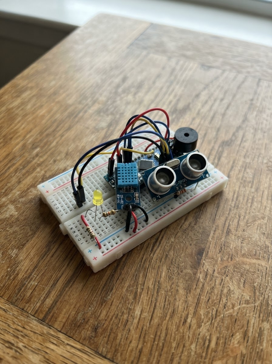
This project builds a detection system that monitors for rapid water level changes and ground vibrations, two key indicators of tsunami activity. The ESP32 microcontroller combines an ultrasonic distance sensor to track water height, a vibration sensor to detect seismic activity, and audio-visual alerts (buzzer and LED) to warn of potential danger.
The guide provides a complete wiring diagram, parts list, and step-by-step assembly instructions for connecting all components safely to the ESP32. The included firmware continuously samples the distance sensor with noise filtering, triggers an alarm when water levels shift suddenly or vibrations are detected, and maintains the alert for a set duration to ensure the warning is noticed.
Wiring diagram

Gather all the parts
Assemble it in 5 steps
1. Make shared power rows
Place the ESP32 beside the breadboard. Use one jumper from ESP32 3V3 to a positive breadboard row and one from ESP32 GND to a ground row. Use another jumper from ESP32 VIN/5V to a separate 5 V row for the ultrasonic sensor. Every ground row used by the parts must connect back to ESP32 GND.
- Keep the 3.3 V and 5 V rows separate; label them with tape if that helps.
- Do not join the ESP32 3V3 row to the 5 V row — 5 V on an ESP32 signal or 3.3 V pin can damage the board.
2. Wire the vibration warning light
Connect the SW-420 VCC pin to 3V3 (power), GND to GND (ground), and DO to GPIO32 (signal). Put the yellow LED across the breadboard center gap: its long leg goes to one end of the 220 Ω resistor, the other resistor end goes to GPIO26 (signal), and its short leg/flat-side leg goes to GND (ground).
- Turn the small screw on the SW-420 module later if normal table movement does not switch the yellow LED on and off.
- Make sure the LED long and short legs are not swapped — reversed LEDs do not light.
3. Wire the water-distance sensor safely
Connect HC-SR04 VCC to the separate 5 V row (power), GND to GND (ground), and TRIG to GPIO25 (signal). Connect HC-SR04 ECHO to one end of the 1 kΩ resistor. Join the other end of that 1 kΩ resistor, one end of the 2 kΩ resistor, and GPIO33 in the same breadboard row (signal). Connect the free end of the 2 kΩ resistor to GND (ground).
- The two resistors make a safe meeting point: 1 kΩ comes from ECHO, 2 kΩ goes to ground, and GPIO33 joins that meeting point.
- Never connect the HC-SR04 ECHO pin straight to an ESP32 pin — its 5 V signal can damage the ESP32. Keep the sensor facing down toward still water and keep its electronics dry.
4. Wire the alarm buzzer
Connect the buzzer SIGNAL or + pin to GPIO27 (signal) and its GND or − pin to GND (ground). If it is an unmarked two-leg buzzer, use the leg marked + for GPIO27 and the other leg for GND.
- This design expects a small 3.3 V active buzzer. An active buzzer makes a sound when it receives a steady on signal.
- Do not use a larger high-current buzzer directly from GPIO27; it can overload the ESP32 pin.
5. Position and test the sensors
Mount the HC-SR04 above the water so its two round openings point straight down and have a clear path to the water surface. Keep the ESP32, breadboard, SW-420 board, LED, and buzzer dry and away from splash zones. Connect the ESP32 to USB, then press Deploy in Schematik. After it starts, the first distance is the reference; move the water surface or sensor by at least 3 cm to hear the 10-second alarm.
- A ruler is useful: raise or lower the water by at least 3 cm between one-second readings. The yellow LED should follow vibration separately from the water alarm.
- This breadboard project is an educational local water-level-change alarm, not a certified tsunami-warning instrument. Keep mains electricity and the USB connection away from water.
Review all connections
1. Connections between "vibration_sensor" and "ESP32"
2. Connections between "ultrasonic_sensor" and "ESP32"
3. Connections between "echo_resistor_bottom" and "ESP32"
4. Connections between "led_resistor" and "ESP32"
5. Connections between "yellow_led" and "ESP32"
6. Connections between "alarm_buzzer" and "ESP32"
7. Connections between "echo_resistor_top" and "ESP32"
Deploy the firmware
#include <Arduino.h>


// Forward declarations
float readDistanceCm();
float medianOfThreeDistances();
void setBuzzer(bool enabled);

const int VIBRATION_PIN = 32;
const int TRIG_PIN = 25;
const int ECHO_PIN = 33;
const int YELLOW_LED_PIN = 26;
const int BUZZER_PIN = 27;

const unsigned long SAMPLE_INTERVAL_MS = 1000;
const unsigned long ALARM_DURATION_MS = 10000;
const float CHANGE_THRESHOLD_CM = 3.0f;
const int BUZZER_CHANNEL = 0;
const int BUZZER_FREQUENCY_HZ = 2000;

float previousDistanceCm = -1.0f;
unsigned long lastSampleMs = 0;
unsigned long alarmUntilMs = 0;

float readDistanceCm() {
  digitalWrite(TRIG_PIN, LOW);
  delayMicroseconds(3);
  digitalWrite(TRIG_PIN, HIGH);
  delayMicroseconds(10);
  digitalWrite(TRIG_PIN, LOW);

  unsigned long duration = pulseIn(ECHO_PIN, HIGH, 30000);
  if (duration == 0) {
    return -1.0f;
  }

  float distance = (duration * 0.0343f) / 2.0f;
  if (distance < 2.0f || distance > 400.0f) {
    return -1.0f;
  }
  return distance;
}

float medianOfThreeDistances() {
  float readings[3];
  int validCount = 0;

  for (int i = 0; i < 3; i++) {
    float reading = readDistanceCm();
    if (reading > 0.0f) {
      readings[validCount++] = reading;
    }
    delay(60);
  }

  if (validCount == 0) {
    return -1.0f;
  }
  if (validCount == 1) {
    return readings[0];
  }
  if (validCount == 2) {
    return (readings[0] + readings[1]) / 2.0f;
  }

  if (readings[0] > readings[1]) {
    float temp = readings[0];
    readings[0] = readings[1];
    readings[1] = temp;
  }
  if (readings[1] > readings[2]) {
    float temp = readings[1];
    readings[1] = readings[2];
    readings[2] = temp;
  }
  if (readings[0] > readings[1]) {
    float temp = readings[0];
    readings[0] = readings[1];
    readings[1] = temp;
  }
  return readings[1];
}

void setBuzzer(bool enabled) {
  if (enabled) {
    ledcWriteTone(BUZZER_CHANNEL, BUZZER_FREQUENCY_HZ);
  } else {
    ledcWriteTone(BUZZER_CHANNEL, 0);
  }
}

void setup() {
  Serial.begin(115200);

  pinMode(VIBRATION_PIN, INPUT);
  pinMode(TRIG_PIN, OUTPUT);
  pinMode(ECHO_PIN, INPUT);
  pinMode(YELLOW_LED_PIN, OUTPUT);
  digitalWrite(YELLOW_LED_PIN, LOW);

  ledcSetup(BUZZER_CHANNEL, BUZZER_FREQUENCY_HZ, 8);
  ledcAttachPin(BUZZER_PIN, BUZZER_CHANNEL);
  setBuzzer(false);

  Serial.println("Tsunami detector started. Waiting for first water-level reading.");
}

void loop() {
  // Most SW-420 modules output HIGH while the sensor is vibrating.
  bool vibrationDetected = digitalRead(VIBRATION_PIN) == HIGH;
  digitalWrite(YELLOW_LED_PIN, vibrationDetected ? HIGH : LOW);

  unsigned long now = millis();
  if (now - lastSampleMs >= SAMPLE_INTERVAL_MS) {
    lastSampleMs = now;
    float currentDistanceCm = medianOfThreeDistances();

    if (currentDistanceCm > 0.0f) {
      if (previousDistanceCm > 0.0f) {
        float changeCm = fabsf(currentDistanceCm - previousDistanceCm);
        Serial.print("Water surface distance: ");
        Serial.print(currentDistanceCm, 1);
        Serial.print(" cm; change: ");
        Serial.print(changeCm, 1);
        Serial.println(" cm");

        if (changeCm >= CHANGE_THRESHOLD_CM) {
          alarmUntilMs = now + ALARM_DURATION_MS;
          Serial.println("Water-level alarm: 3 cm or greater change detected.");
        }
      } else {
        Serial.print("Reference water-surface distance: ");
        Serial.print(currentDistanceCm, 1);
        Serial.println(" cm");
      }
      previousDistanceCm = currentDistanceCm;
    } else {
      Serial.println("No usable ultrasonic reading; check that the sensor faces the water.");
    }
  }

  bool alarmActive = (long)(alarmUntilMs - now) > 0;
  setBuzzer(alarmActive);
}
Remix this project
Make it yours in one click
Open a full copy of this project in your own Schematik workspace — diagram, code, parts, and assembly steps included. Swap the sensor, add features, or redesign the whole thing with AI. The author's original stays untouched.