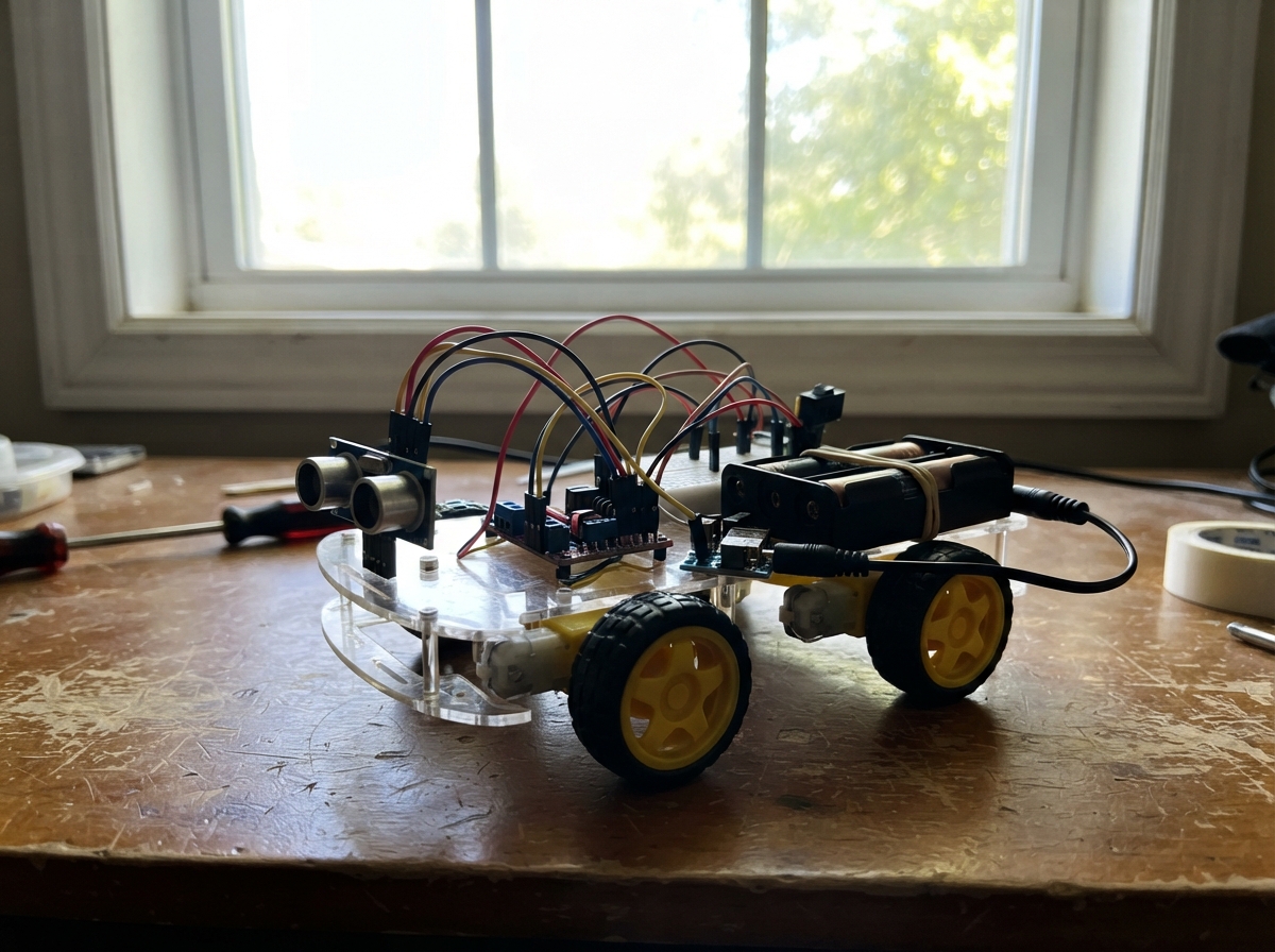
This project builds a four-wheel robot car that navigates autonomously by detecting obstacles with an ultrasonic sensor and steering around them. The HC-SR04 sensor continuously measures distance ahead, triggering the Arduino to reverse and turn the car away when obstacles get too close, creating a simple but effective obstacle-avoidance behavior.
The guide provides a complete wiring diagram, parts list, and step-by-step assembly instructions for mounting the four TT motors, configuring the power system with the buck converter, and connecting the L298N motor driver to the Arduino control board. Included firmware handles motor control and distance measurement, ready to upload and test.
Wiring diagram
Gather all the parts
Assemble it in 5 steps
1. Mount the motors and wheels
Put the four white gear motors on the car chassis: one at each corner. Push a wheel onto the outward-facing shaft of each motor. Keep the two motors on the left side together and the two motors on the right side together.
- If one wheel later spins the wrong way, swapping that motor's two wires reverses it.
- Do not let loose motor wires touch while the batteries are installed; the wires can get hot.
2. Set the two voltage modules before wiring the car
With the battery holder switched off, connect its red VOUT wire to VIN+ and black GND wire to VIN- on both voltage modules. Use a multimeter and briefly switch on the holder: set motor_buck to exactly 6.0 V and logic_buck to exactly 5.0 V before connecting the Arduino, L298N board, or motors.
- Turn each small adjustment screw gently while measuring between VOUT+ and VOUT-.
- Mark the 6 V module “MOTORS” and the 5 V module “UNO” so they cannot be mixed up.
- A voltage module set too high can damage the motors or Arduino. Never adjust it while it is connected to the car electronics.
3. Wire the L298N board and the four motors
Remove the small 5V-EN jumper from the L298N board. Connect motor_buck VOUT+ to the L298N 12V terminal (motor power) and motor_buck VOUT- to L298N GND (ground). Connect logic_buck VOUT+ to L298N 5V (logic power). Leave the ENA and ENB jumpers fitted. Connect both left motors in parallel: one wire from each left motor to OUT1 and the other wire from each left motor to OUT2. Connect both right motors the same way: one wire from each right motor to OUT3 and the other wire from each right motor to OUT4.
- Tighten the L298N screw terminals so vibration cannot shake a wire loose.
- The two motors on each side must turn the car in the same direction; swap both wires on only the motor that fights its partner.
- Do not connect any motor directly to an Arduino pin; the motor current can permanently damage the board.
- Keep the motor supply at 6 V. Connecting the 12 V battery directly to the L298N 12V terminal can damage the small white motors.
4. Wire the Arduino control and sensor leads
Connect logic_buck VOUT+ to the Uno 5V pin (power) and logic_buck VOUT- to an Uno GND pin (ground). Connect L298N GND to the same Uno GND line (ground). Connect L298N IN1 to Uno D7 (left direction), IN2 to Uno D6 (left direction), IN3 to Uno D5 (right direction), and IN4 to Uno D4 (right direction). Connect the HC-SR04 VCC to Uno 5V (power), GND to Uno GND (ground), TRIG to D8 (signal), and ECHO to D9 (signal).
- Put the HC-SR04 at the front of the chassis with its two round eyes pointing straight ahead.
- Use short, different-colored wires for the four Uno-to-L298N control connections.
- Do not connect the regulated 5 V output to the Uno VIN pin; use the Uno 5V pin because the module is already set to 5 V.
- Make sure VCC and GND are not swapped on the sensor; swapped power can damage it.
5. Do the first safe power check
Lift the car so all four wheels are clear of the table. Install eight matching AA batteries, switch on the battery holder, and check that nothing becomes hot. The car will wait briefly, then its wheels should begin turning. Switch it off before putting it on the floor.
- If the car drives backward when the program intends to drive forward, swap both wires on both motors of that side.
- Hold your hand about 15 cm in front of the sensor after testing wheel direction; the car should reverse and turn away.
- Keep fingers, hair, and loose clothing away from spinning wheels.
- Use only matching AA batteries of the same type and charge level; mixed batteries can leak or become hot.
Review all connections
1. Connections between "battery_pack" and "Arduino"
2. Connections between "motor_buck" and "Arduino"
3. Connections between "logic_buck" and "Arduino"
4. Connections between "driver" and "Arduino"
5. Connections between "ultrasonic" and "Arduino"
Deploy the firmware
// Automatic obstacle-avoiding car for an Arduino Uno and a common L298N module.
// Leave the ENA and ENB jumpers fitted on the L298N board.
const byte LEFT_IN1_PIN = 7;
const byte LEFT_IN2_PIN = 6;
const byte RIGHT_IN3_PIN = 5;
const byte RIGHT_IN4_PIN = 4;
const byte TRIG_PIN = 8;
const byte ECHO_PIN = 9;

const int STOP_DISTANCE_CM = 25;

void stopMotors() {
  digitalWrite(LEFT_IN1_PIN, LOW);
  digitalWrite(LEFT_IN2_PIN, LOW);
  digitalWrite(RIGHT_IN3_PIN, LOW);
  digitalWrite(RIGHT_IN4_PIN, LOW);
}

void driveForward() {
  digitalWrite(LEFT_IN1_PIN, HIGH);
  digitalWrite(LEFT_IN2_PIN, LOW);
  digitalWrite(RIGHT_IN3_PIN, HIGH);
  digitalWrite(RIGHT_IN4_PIN, LOW);
}

void driveBackward() {
  digitalWrite(LEFT_IN1_PIN, LOW);
  digitalWrite(LEFT_IN2_PIN, HIGH);
  digitalWrite(RIGHT_IN3_PIN, LOW);
  digitalWrite(RIGHT_IN4_PIN, HIGH);
}

void turnLeft() {
  digitalWrite(LEFT_IN1_PIN, LOW);
  digitalWrite(LEFT_IN2_PIN, HIGH);
  digitalWrite(RIGHT_IN3_PIN, HIGH);
  digitalWrite(RIGHT_IN4_PIN, LOW);
}

int readDistanceCm() {
  digitalWrite(TRIG_PIN, LOW);
  delayMicroseconds(3);
  digitalWrite(TRIG_PIN, HIGH);
  delayMicroseconds(12);
  digitalWrite(TRIG_PIN, LOW);

  unsigned long echoMicroseconds = pulseIn(ECHO_PIN, HIGH, 30000UL);
  if (echoMicroseconds == 0) {
    return 400;
  }
  return (int)(echoMicroseconds / 58UL);
}

void setup() {
  pinMode(LEFT_IN1_PIN, OUTPUT);
  pinMode(LEFT_IN2_PIN, OUTPUT);
  pinMode(RIGHT_IN3_PIN, OUTPUT);
  pinMode(RIGHT_IN4_PIN, OUTPUT);
  pinMode(TRIG_PIN, OUTPUT);
  pinMode(ECHO_PIN, INPUT);
  stopMotors();
  delay(500);
}

void loop() {
  int distanceCm = readDistanceCm();

  if (distanceCm > 0 && distanceCm < STOP_DISTANCE_CM) {
    stopMotors();
    delay(150);
    driveBackward();
    delay(350);
    stopMotors();
    delay(100);
    turnLeft();
    delay(450);
    stopMotors();
    delay(100);
  } else {
    driveForward();
    delay(70);
  }
}
Remix this project
Make it yours in one click
Open a full copy of this project in your own Schematik workspace, diagram, code, parts, and assembly steps included. Swap the sensor, add features, or redesign the whole thing with AI. The author's original stays untouched.