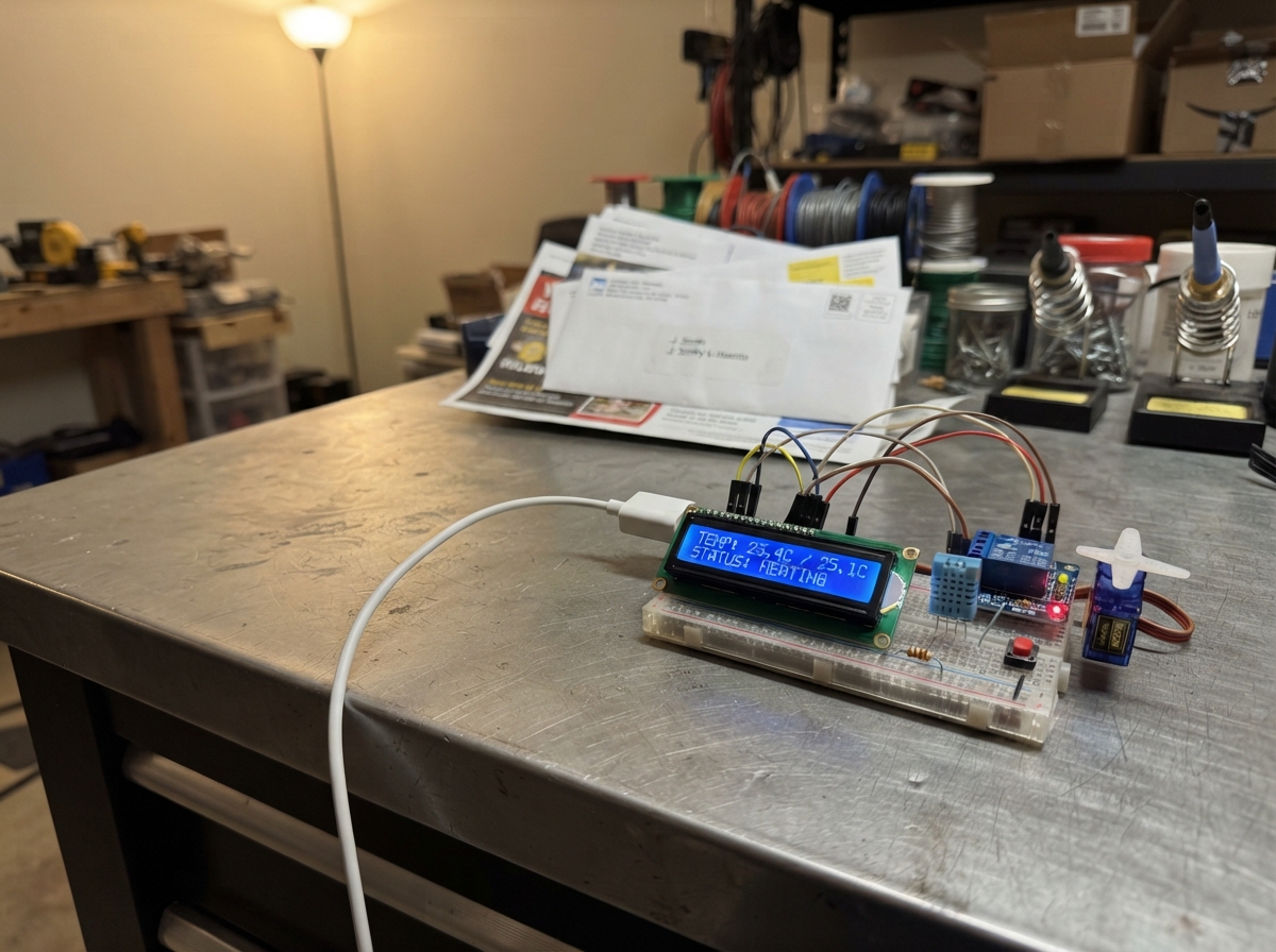
This dual-channel temperature controller uses an Arduino Uno to monitor ambient temperature with a DHT11 sensor and maintain it within a target range using a relay-controlled cooling system and servo-actuated vent. The guide provides a complete wiring diagram, parts list, and step-by-step assembly instructions that walk through breadboard setup, sensor and display connections, button integration, and relay module configuration.
Following this guide, makers will build a functioning temperature regulation system with a 16x2 LCD display for real-time feedback, three push buttons for control, and automated cooling activation. The firmware handles debounced button input, temperature sensing, relay switching, and servo control to open and close the cooling vent based on user-set temperature targets.
Wiring diagram
Gather all the parts
Assemble it in 7 steps
1. Prepare the breadboard power rails
Unplug USB. Connect Mega 5V to a red rail and GND to a blue rail. Bridge split rails if needed. Keep the relay module beside the breadboard.
- Never put mains voltage or air-conditioner power wiring on the breadboard. This is a low-voltage control prototype, not a finished AC safety controller.
2. Connect the temperature sensor
Connect DHT11 VCC to 5V, GND to the ground rail, and DATA to Mega D2. Connect the 4.7 kΩ resistor between DATA and 5V. Follow module pin labels, not cable colours. For a bare four-pin DHT11 viewed from the front grille with legs downward, pins left to right are VCC, DATA, unused, GND. Leave the unused pin disconnected. Readings update every two seconds; accuracy is about ±2 C.
3. Connect the four-pin LCD
Use a 16x2 LCD with an I2C backpack: VCC to 5V, GND to ground, SDA to D20 (data), SCL to D21 (clock). Firmware uses address 0x27. Adjust the backpack contrast screw if the text is faint. A bare 16-pin LCD needs a backpack for this wiring.
4. Add the three push buttons
Put each momentary button across the breadboard centre gap. Use contacts on opposite switched sides: one to ground and the other to D22 for ON/OFF, D23 for +, or D24 for -. Legs on the same internally joined side will not work. Internal pull-ups are enabled.
5. Connect the relay control side only
Use the 5V LOW-trigger dual relay module. Leave its factory VCC/JD-VCC jumper installed. VCC goes to 5V, GND to ground, IN1 to D26 (cooling), IN2 to D27 (fan). Put one 10 kΩ resistor from each input to 5V to keep it off during reset. Leave all screw terminals disconnected.
- Do not connect a compressor directly to these hobby relays. A qualified HVAC technician must design an approved isolated interface and retain the equipment's pressure, overload and other safety controls.
6. Check the low-voltage prototype
Check for shorts between power rails. Power the Mega from USB and the servo from its separate regulated 5V supply for this unloaded test. The controller starts OFF at 24 C. ON/OFF toggles operation; + and - adjust 16–30 C. Fan relay is on while enabled with a healthy sensor. Cooling starts 1 C above target and stops at target, with a three-minute delay after boot and every cooling stop. Sensor failure turns both relays off. Settings reset after power loss.
- Confirm both relays stay off during reset before considering any external control interface. USB power here is only for the Mega, LCD, sensor and unloaded relay module.
7. Connect and test the cooling vent servo
Use an SG90 micro servo for a lightweight model vent. Signal (usually orange/yellow) goes to Mega D6. Servo red goes to the separate regulated 5V adapter positive output; brown/black goes to adapter ground. Connect adapter ground to Mega GND. Use a supply rated at least 1A with accessible insulated low-voltage output leads. Keep its positive output separate from the Mega 5V rail; never power the servo from the Mega. The servo moves to 90 degrees only while the cooling relay is ON; it returns to 10 degrees when cooling stops, the controller is OFF, or the sensor fails. During the three-minute cooling delay it stays closed.
- Disconnect the vent linkage for the first test. Fit the horn after checking the closed and open positions; adjust VENT_CLOSED and VENT_OPEN in firmware to avoid mechanical stops. Do not force a real AC damper with this small hobby servo.
- Keep mains connections enclosed inside the purchased adapter. Never cut or handle mains wiring. Disconnect both supplies before changing connections.
Review all connections
1. Connections between "temperature" and "Arduino"
2. Connections between "sensorPullup" and "Arduino"
3. Connections between "lcd" and "Arduino"
4. Connections between "powerButton" and "Arduino"
5. Connections between "plusButton" and "Arduino"
6. Connections between "minusButton" and "Arduino"
7. Connections between "relays" and "Arduino"
8. Connections between "relayPullup1" and "Arduino"
9. Connections between "relayPullup2" and "Arduino"
10. Connections between "ventServo" and "Arduino"
11. Connections between "servoSupply" and "Arduino"
Deploy the firmware
#include <Arduino.h>
#include <Wire.h>
#include <DHT.h>
#include <LiquidCrystal_I2C.h>
#include <math.h>
#include <Servo.h>
Servo vent;
const uint8_t VENT_PIN=6, VENT_CLOSED=10, VENT_OPEN=90;
DHT sensor(2,DHT11);
LiquidCrystal_I2C lcd(0x27,16,2);
const uint8_t COOL=26,FAN=27;
const unsigned long DELAY_MS=180000UL;
bool enabled=false,cooling=false,valid=false;
int target=24;
float temperature=0;
unsigned long stopped=0,requested=0;
char oldLines[2][17]={{0},{0}};
struct Button {
 Button(uint8_t p):pin(p){}
 uint8_t pin; bool raw=HIGH,stable=HIGH; unsigned long changed=0;
 bool pressed(unsigned long now) {
  bool r=digitalRead(pin);
  if(r!=raw){raw=r;changed=now;}
  if(r!=stable && now-changed>=35){stable=r;return r==LOW;}
  return false;
 }
};
Button buttons[3]={{22},{23},{24}};
void line(uint8_t row,const char* text){
 char padded[17]; memset(padded,' ',16); padded[16]=0;
 size_t n=strlen(text); if(n>16)n=16; memcpy(padded,text,n);
 if(strcmp(padded,oldLines[row])){lcd.setCursor(0,row);lcd.print(padded);strcpy(oldLines[row],padded);}
}
void setup(){
 vent.write(VENT_CLOSED);vent.attach(VENT_PIN);
 digitalWrite(COOL,HIGH);digitalWrite(FAN,HIGH);
 pinMode(COOL,OUTPUT);pinMode(FAN,OUTPUT);
 for(auto &b:buttons)pinMode(b.pin,INPUT_PULLUP);
 Wire.begin();lcd.init();lcd.backlight();
 sensor.begin();requested=millis();stopped=millis();
}
void loop(){
 unsigned long now=millis();
 if(buttons[0].pressed(now))enabled=!enabled;
 if(buttons[1].pressed(now) && target<30)target++;
 if(buttons[2].pressed(now) && target>16)target--;
 if(now-requested>=2000){
  float t=sensor.readTemperature();
  valid=isfinite(t) && t>=0 && t<=50;
  if(valid)temperature=t;
  requested=now;
 }
 bool wanted=cooling;
 if(!enabled || !valid)wanted=false;
 else if(cooling && temperature<=target)wanted=false;
 else if(!cooling && temperature>=target+1 && now-stopped>=DELAY_MS)wanted=true;
 if(cooling && !wanted)stopped=now;
 if(cooling!=wanted)vent.write(wanted?VENT_OPEN:VENT_CLOSED);
 cooling=wanted;
 digitalWrite(COOL,cooling?LOW:HIGH);
 digitalWrite(FAN,(enabled && valid)?LOW:HIGH);
 char text[24],number[10];
 if(valid){dtostrf(temperature,4,1,number);snprintf(text,sizeof(text),"T:%sC Set:%d",number,target);}
 else snprintf(text,sizeof(text),"Sensor error");
 line(0,text);
 if(!enabled)line(1,"OFF");
 else if(!valid)line(1,"FAULT: relays OFF");
 else if(cooling)line(1,"COOL ON  FAN ON");
 else if(now-stopped<DELAY_MS){snprintf(text,sizeof(text),"WAIT %lus FAN ON",(DELAY_MS-(now-stopped)+999)/1000);line(1,text);}
 else line(1,"READY    FAN ON");
}
Remix this project
Make it yours in one click
Open a full copy of this project in your own Schematik workspace, diagram, code, parts, and assembly steps included. Swap the sensor, add features, or redesign the whole thing with AI. The author's original stays untouched.