Community project
USB Bluetooth Call Bridge
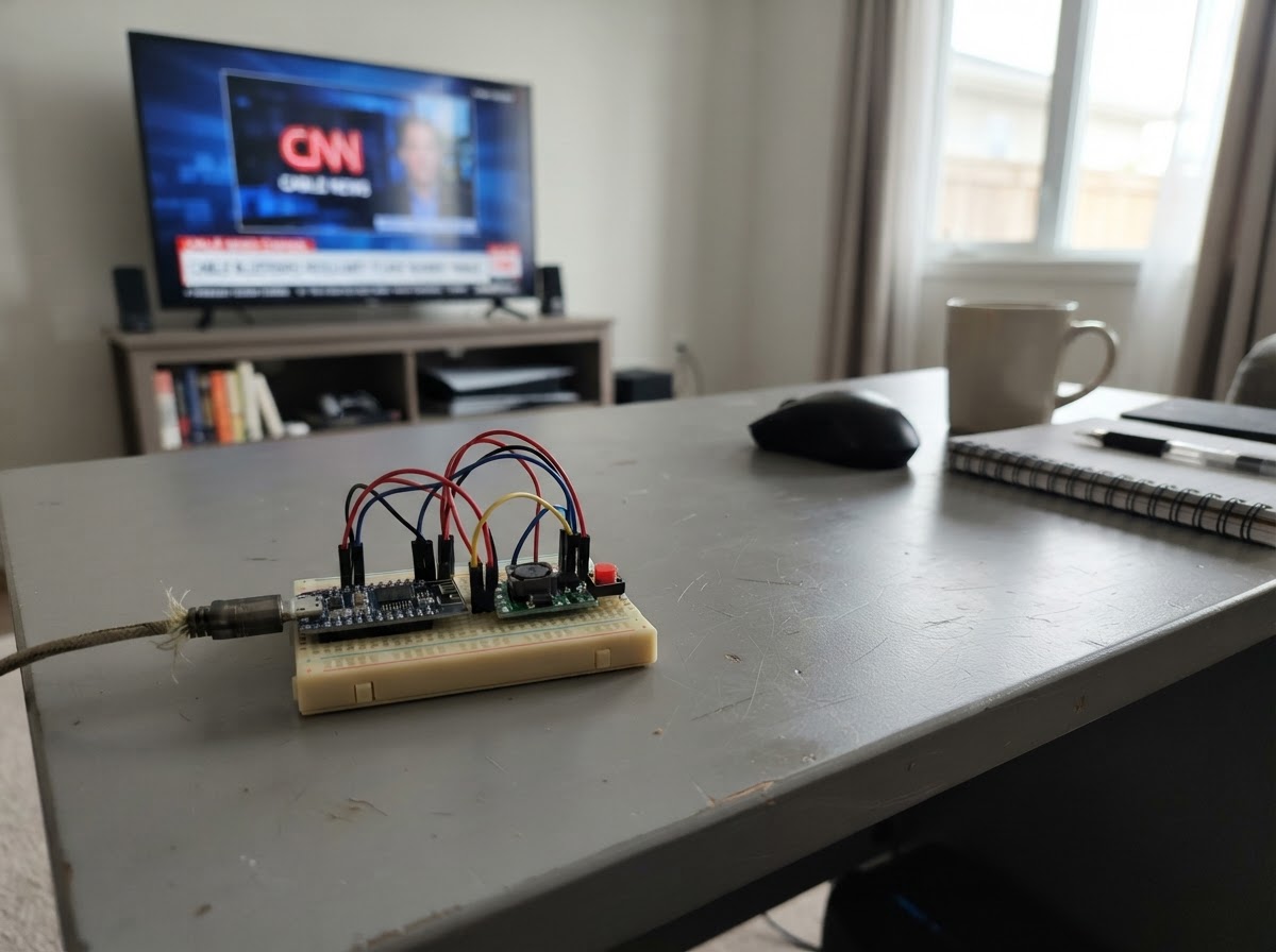
This project bridges Bluetooth audio calls to a computer via USB, enabling hands-free calling through a wireless headset or speaker connected to the BM83 module. The ESP32 acts as an intermediary, routing audio between the Bluetooth module and a USB audio device while managing call control through a simple push button.
The guide provides a complete wiring diagram, parts list, and step-by-step assembly instructions for connecting the BM83 Bluetooth audio module, power regulation circuit, and control button to the ESP32. Included firmware implements I2S audio streaming and USB audio class support, allowing the device to appear as a standard audio input/output on any computer.
Wiring diagram

Gather all the parts
Assemble it in 6 steps
1. 准备 USB 供电与共地
用 ESP32‑S3‑DevKitC‑1 的 USB‑C 接口连接电脑。把开发板的 5V 针脚接到 3.6 V 降压模块的 VIN,把开发板 GND 接到降压模块 GND,并把 BM83 的 GND 也接到同一条地线;这些线分别给模块供电并提供共同回路。
- 先不要接手机或戴耳机;先确认所有黑色地线在同一排。
- 不要把开发板的 5V 直接接到 BM83 的 BAT_IN;过高电压可能损坏蓝牙模块。
2. 给 BM83 接上 3.6 V
把降压模块 VOUT 调整并用万用表确认是 3.6 V 后,再把 VOUT 接到 BM83 的 BAT_IN。这个稳压输出只给 BM83 供电。
- 调整前先断开 BM83;测量 VOUT 与 GND 之间的电压,确认稳定为 3.6 V。
- 如果 VOUT 不是约 3.6 V,不要接 BM83;错误电压会使模块无法工作或损坏。
3. 接上蓝牙开机按钮
把按钮的一脚 A 接 BM83 的 PWR_MFB,另一脚 B 接 3.6 V 降压模块 VOUT。按下按钮时,BM83 会得到开机或唤醒脉冲。
- 四脚轻触开关中,同一侧的两脚通常已经相通;请使用相对两侧各一脚。
- 不要把 PWR_MFB 接到 5V;它只能接 BM83 的 3.6 V 逻辑/供电侧。
4. 连接四根数字音频线
用短导线依次连接:BM83 SCLK1 → ESP32 GPIO12(音频节拍),BM83 RFS1 → GPIO13(每个音频字的标记),BM83 DR1 → GPIO11(电脑播放送往手机的声音),BM83 DT1 → GPIO10(手机通话送回电脑的声音)。
- 四根线尽量短并远离降压模块电感,能减少杂音。
- 不要把 DR1 与 DT1 接反;接反后电脑播放和录音的方向会颠倒。
5. 连接蓝牙控制线
交叉连接串口:BM83 UART_RXD → ESP32 GPIO43(控制命令进入 BM83),BM83 UART_TXD → ESP32 GPIO44(BM83 状态返回 ESP32)。
- RX 表示接收,所以要接对方的 TX;两根线必须交叉。
- 不要把 BM83 的 3.3 V 串口线接到 5 V;5 V 信号可能损坏模块输入。
6. 保留 USB 数据线并开始使用
不要在 ESP32 GPIO19 与 GPIO20 上另接任何线;它们保留给 USB‑C 的电脑声卡数据。检查完所有供电线后,用 USB‑C 接电脑,按一下 BM83 按钮并让手机以蓝牙耳机方式配对。
- 电脑应出现一个带播放和录音的 USB Audio 设备;手机通话时,播放进入设备的声音会作为通话上行,录音端收到的是通话下行。
- 第一次通电前再次确认 VCC 和 GND 没有接反;接反可能损坏开发板、降压模块或 BM83。
Review all connections
1. Connections between "reg_3v6_1" and "ESP32"
2. Connections between "bm83_1" and "ESP32"
3. Connections between "power_button_1" and "ESP32"
Deploy the firmware
#include <stddef.h>
#include <stdint.h>
#include "esp_err.h"
#include "esp_log.h"
#include "driver/i2s_std.h"
#include "usb_device_uac.h"

#define AUDIO_SAMPLE_RATE_HZ 16000
#define I2S_BCLK_GPIO        12
#define I2S_WS_GPIO          13
#define I2S_DOUT_GPIO        11
#define I2S_DIN_GPIO         10

static const char *TAG = "hfp_usb_bridge";
static i2s_chan_handle_t tx_chan;
static i2s_chan_handle_t rx_chan;

static esp_err_t output_cb(uint8_t *buf, size_t len, void *ctx)
{
    size_t bytes_written = 0;
    return i2s_channel_write(tx_chan, buf, len, &bytes_written, 20);
}

static esp_err_t input_cb(uint8_t *buf, size_t len, size_t *bytes_read, void *ctx)
{
    return i2s_channel_read(rx_chan, buf, len, bytes_read, 20);
}

void app_main(void)
{
    i2s_chan_config_t channel_cfg = I2S_CHANNEL_DEFAULT_CONFIG(I2S_NUM_0, I2S_ROLE_MASTER);
    ESP_ERROR_CHECK(i2s_new_channel(&channel_cfg, &tx_chan, &rx_chan));

    i2s_std_config_t i2s_cfg = {
        .clk_cfg = I2S_STD_CLK_DEFAULT_CONFIG(AUDIO_SAMPLE_RATE_HZ),
        .slot_cfg = I2S_STD_MSB_SLOT_DEFAULT_CONFIG(I2S_DATA_BIT_WIDTH_16BIT, I2S_SLOT_MODE_MONO),
        .gpio_cfg = {
            .mclk = I2S_GPIO_UNUSED,
            .bclk = I2S_BCLK_GPIO,
            .ws = I2S_WS_GPIO,
            .dout = I2S_DOUT_GPIO,
            .din = I2S_DIN_GPIO,
            .invert_flags = { .mclk_inv = false, .bclk_inv = false, .ws_inv = false },
        },
    };
    ESP_ERROR_CHECK(i2s_channel_init_std_mode(tx_chan, &i2s_cfg));
    ESP_ERROR_CHECK(i2s_channel_init_std_mode(rx_chan, &i2s_cfg));
    ESP_ERROR_CHECK(i2s_channel_enable(tx_chan));
    ESP_ERROR_CHECK(i2s_channel_enable(rx_chan));

    const uac_device_config_t uac_cfg = {
        .output_cb = output_cb,
        .input_cb = input_cb,
        .cb_ctx = NULL,
    };
    ESP_ERROR_CHECK(uac_device_init(&uac_cfg));
    ESP_LOGI(TAG, "USB Audio to BM83 I2S bridge started at %d Hz", AUDIO_SAMPLE_RATE_HZ);
}
Remix this project
Make it yours in one click
Open a full copy of this project in your own Schematik workspace — diagram, code, parts, and assembly steps included. Swap the sensor, add features, or redesign the whole thing with AI. The author's original stays untouched.