Community project
Voice AI Assistant
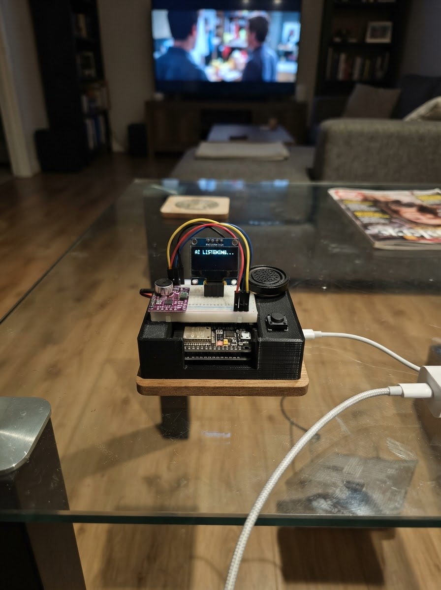
This project builds a voice-controlled AI assistant powered by an ESP32 microcontroller. The device captures audio through an I²S microphone, sends it to an AI model via a secure Windows bridge, and plays back responses through a speaker. An OLED display shows status and confirmation prompts, while a push button triggers recording.
The guide provides a complete wiring diagram showing connections between the ESP32, INMP441 microphone module, MAX98357A amplifier, SSD1306 display, speaker, and control button. You'll get a full parts list, step-by-step assembly instructions, and Arduino firmware that handles WiFi connectivity, I²S audio streaming, and secure communication with your AI backend.
Wiring diagram

Gather all the parts
Assemble it in 6 steps
1. Togli alimentazione e prepara la scheda
Scollega l’ESP32-S3 dal cavo USB. Appoggialo sul tavolo con la presa USB rivolta verso di te e prepara una breadboard, cavetti maschio-femmina e i cinque moduli.
- Non collegare ancora il cavo USB: così non puoi unire per errore due fili alimentati.
- Non alimentare il microfono, lo schermo o l’amplificatore con 5 V: questi moduli in questo progetto usano 3,3 V e una tensione maggiore può danneggiarli.
2. Collega lo schermino
Collega OLED VCC → 3V3 (power), OLED GND → GND (ground), OLED SDA → GPIO8 (data) e OLED SCL → GPIO9 (clock). Sullo schermino i nomi sono stampati vicino ai quattro pin.
- Se il display resta completamente nero, controlla prima che VCC e GND non siano invertiti.
- VCC e GND scambiati possono danneggiare lo schermino.
3. Collega il microfono
Collega INMP441 VDD → 3V3 (power), INMP441 GND → GND (ground), INMP441 SCK → GPIO14 (audio timing), INMP441 WS → GPIO15 (audio timing), INMP441 SD → GPIO16 (voice signal) e INMP441 L/R → GND (left microphone channel).
- Tieni i tre cavetti SCK, WS e SD corti e lontani dai fili dell’altoparlante: questo aiuta a non raccogliere disturbi.
- Non usare il pin 5 V della scheda per VDD: il microfono è un modulo a 3,3 V.
4. Collega amplificatore e altoparlante
Collega MAX98357A VIN → 3V3 (power), MAX98357A GND → GND (ground), MAX98357A BCLK → GPIO14 (audio timing), MAX98357A LRC → GPIO15 (audio timing), MAX98357A DIN → GPIO17 (audio signal) e MAX98357A SD → 3V3 (enable). Poi collega MAX98357A SPK+ → altoparlante POS (sound output) e MAX98357A SPK− → altoparlante NEG (sound return).
- GPIO14 e GPIO15 sono condivisi con il microfono: ogni filo va nello stesso punto elettrico dei rispettivi BCLK/SCK e LRC/WS.
- I due fili SPK+ e SPK− vanno solo all’altoparlante, non a GND.
- Non collegare nessuno dei fili dell’altoparlante a GND: l’uscita dell’amplificatore usa entrambi i fili e un collegamento a massa può danneggiarlo.
5. Collega il pulsante di comando
Metti il pulsante a cavallo della fessura centrale della breadboard. Collega un lato del pulsante → GPIO4 (signal) e il lato opposto → GND (ground). Premi una volta per parlare; se lo schermo chiede di confermare un’azione sul PC, premi di nuovo.
- Un pulsante a quattro piedini ha spesso due piedini già uniti per lato: usa due piedini che si trovano su lati opposti del pulsante.
- Se il pulsante sembra sempre premuto, probabilmente hai scelto due piedini dello stesso lato.
6. Alimenta e configura il collegamento sicuro
Ricontrolla tutti i fili, poi collega l’ESP32-S3 al PC con USB. Prima del Deploy inserisci nel firmware il nome e la password del tuo Wi‑Fi e l’indirizzo HTTPS del ponte Windows. La chiave OpenAI deve restare nel ponte Windows, mai nel dispositivo.
- Il ponte deve accettare audio PCM mono a 16 kHz su /voice e restituire JSON con testo, URL opzionale dell’audio e, per azioni PC, un testo di azione con confirmation_required impostato a true.
- Limita il ponte a una lista di azioni consentite e chiedi sempre conferma anche sul PC per azioni importanti.
- Non inserire la chiave OpenAI nel firmware: chiunque possa leggere il dispositivo potrebbe copiarla.
Review all connections
1. Connections between "oled_1" and "ESP32"
2. Connections between "mic_1" and "ESP32"
3. Connections between "amp_1" and "ESP32"
4. Connections between "button_1" and "ESP32"
Deploy the firmware
#include <Arduino.h>
#include <WiFi.h>
#include <HTTPClient.h>
#include <Wire.h>
#include <Adafruit_GFX.h>
#include <Adafruit_SSD1306.h>
#include <ArduinoJson.h>
#include "driver/i2s.h"

// Enter your network and the HTTPS address of your Windows bridge here.
// Keep the OpenAI API key ONLY in the Windows bridge, never in this sketch.

// Forward declarations
void showLines(const String &title, const String &body, bool confirm);
void initI2S();
bool connectWiFi();
void playPcm(HTTPClient &http);
void requestSpeech(const String &url);
void submitConfirmation();
void recordAndAsk();

const char *WIFI_SSID = "YOUR_WIFI_NAME";
const char *WIFI_PASSWORD = "YOUR_WIFI_PASSWORD";
const char *BRIDGE_URL = "https://YOUR-WINDOWS-BRIDGE/voice";

// The Windows bridge should pass this profile as the system instruction to its AI model.
const char *ASSISTANT_PROFILE = "expert_reasoning_hardware";
const char *ASSISTANT_CAPABILITIES = "complex_tasks,compare_alternatives,choose_best_with_reasons,hardware_projects,circuit_design,firmware,step_by_step_build";

constexpr int OLED_SDA = 8;
constexpr int OLED_SCL = 9;
constexpr int I2S_BCLK = 14;
constexpr int I2S_LRCLK = 15;
constexpr int I2S_MIC_DIN = 16;
constexpr int I2S_AMP_DOUT = 17;
constexpr int BUTTON_PIN = 4;
constexpr int SCREEN_WIDTH = 128;
constexpr int SCREEN_HEIGHT = 64;
constexpr int SAMPLE_RATE = 16000;
constexpr uint32_t RECORD_MS = 4000;
constexpr i2s_port_t I2S_PORT = I2S_NUM_0;

Adafruit_SSD1306 display(SCREEN_WIDTH, SCREEN_HEIGHT, &Wire, -1);
String pendingAction;
bool awaitingConfirmation = false;

void showLines(const String &title, const String &body, bool confirm = false) {
  display.clearDisplay();
  display.setTextColor(SSD1306_WHITE);
  display.setTextSize(1);
  display.setCursor(0, 0);
  display.println(title);
  display.drawLine(0, 10, 127, 10, SSD1306_WHITE);
  display.setCursor(0, 15);
  String line;
  for (size_t i = 0; i < body.length(); ++i) {
    char c = body[i];
    line += c;
    if (line.length() >= 20 || c == '\n') {
      display.println(line);
      line = "";
    }
  }
  if (line.length()) display.println(line);
  if (confirm) {
    display.setCursor(0, 54);
    display.print("Premi per confermare");
  }
  display.display();
}

void initI2S() {
  i2s_config_t config = {};
  config.mode = (i2s_mode_t)(I2S_MODE_MASTER | I2S_MODE_RX | I2S_MODE_TX);
  config.sample_rate = SAMPLE_RATE;
  config.bits_per_sample = I2S_BITS_PER_SAMPLE_32BIT;
  config.channel_format = I2S_CHANNEL_FMT_ONLY_LEFT;
  config.communication_format = I2S_COMM_FORMAT_STAND_I2S;
  config.intr_alloc_flags = 0;
  config.dma_buf_count = 8;
  config.dma_buf_len = 256;
  config.use_apll = false;
  config.tx_desc_auto_clear = true;
  config.fixed_mclk = 0;
  i2s_driver_install(I2S_PORT, &config, 0, nullptr);

  i2s_pin_config_t pins = {};
  pins.bck_io_num = I2S_BCLK;
  pins.ws_io_num = I2S_LRCLK;
  pins.data_out_num = I2S_AMP_DOUT;
  pins.data_in_num = I2S_MIC_DIN;
  i2s_set_pin(I2S_PORT, &pins);
  i2s_zero_dma_buffer(I2S_PORT);
}

bool connectWiFi() {
  if (WiFi.status() == WL_CONNECTED) return true;
  showLines("Connessione Wi-Fi", "Attendi...");
  WiFi.begin(WIFI_SSID, WIFI_PASSWORD);
  unsigned long start = millis();
  while (WiFi.status() != WL_CONNECTED && millis() - start < 15000) delay(100);
  return WiFi.status() == WL_CONNECTED;
}

void playPcm(HTTPClient &http) {
  WiFiClient *stream = http.getStreamPtr();
  uint8_t buffer[512];
  while (http.connected()) {
    int available = stream->available();
    if (available <= 0) {
      delay(1);
      continue;
    }
    int got = stream->readBytes(buffer, min(available, (int)sizeof(buffer)));
    size_t written = 0;
    i2s_write(I2S_PORT, buffer, got, &written, portMAX_DELAY);
  }
}

void requestSpeech(const String &url) {
  if (url.length() == 0) return;
  HTTPClient http;
  http.begin(url);
  int status = http.GET();
  if (status == HTTP_CODE_OK) playPcm(http);
  http.end();
}

void submitConfirmation() {
  if (!connectWiFi()) {
    showLines("Wi-Fi assente", "Controlla rete e password");
    return;
  }
  showLines("Conferma inviata", "Il PC puo eseguire: " + pendingAction);
  HTTPClient http;
  String endpoint = String(BRIDGE_URL);
  int slash = endpoint.lastIndexOf('/');
  if (slash >= 0) endpoint = endpoint.substring(0, slash) + "/confirm";
  http.begin(endpoint);
  http.addHeader("Content-Type", "application/json");
  StaticJsonDocument<384> doc;
  doc["action"] = pendingAction;
  doc["confirmed"] = true;
  String request;
  serializeJson(doc, request);
  int status = http.POST(request);
  awaitingConfirmation = false;
  pendingAction = "";
  if (status < 200 || status >= 300) showLines("Errore ponte", "Il PC non ha accettato la conferma");
  else showLines("Fatto", "Azione confermata sul PC");
  http.end();
}

void recordAndAsk() {
  if (!connectWiFi()) {
    showLines("Wi-Fi assente", "Inserisci rete e password nel codice");
    return;
  }
  showLines("Ascolto", "Parla ora per 4 secondi...");
  const size_t samples = (SAMPLE_RATE * RECORD_MS) / 1000;
  const size_t bytesNeeded = samples * sizeof(int16_t);
  uint8_t *pcm = (uint8_t *)malloc(bytesNeeded);
  if (!pcm) {
    showLines("Memoria insufficiente", "Riavvia il dispositivo");
    return;
  }

  size_t produced = 0;
  int32_t i2sBuffer[128];
  while (produced < bytesNeeded) {
    size_t received = 0;
    i2s_read(I2S_PORT, i2sBuffer, sizeof(i2sBuffer), &received, portMAX_DELAY);
    for (size_t i = 0; i < received / sizeof(int32_t) && produced < bytesNeeded; ++i) {
      int16_t sample = (int16_t)(i2sBuffer[i] >> 14);
      pcm[produced++] = sample & 0xFF;
      pcm[produced++] = (sample >> 8) & 0xFF;
    }
  }

  showLines("Sto chiedendo", "Invio la voce al ponte...");
  HTTPClient http;
  http.begin(BRIDGE_URL);
  http.addHeader("Content-Type", "application/octet-stream");
  http.addHeader("X-Audio-Format", "pcm_s16le");
  http.addHeader("X-Sample-Rate", "16000");
  // The bridge can use these headers to select its strongest reasoning model and system prompt.
  http.addHeader("X-Assistant-Profile", ASSISTANT_PROFILE);
  http.addHeader("X-Assistant-Capabilities", ASSISTANT_CAPABILITIES);
  int status = http.POST(pcm, bytesNeeded);
  free(pcm);
  if (status != HTTP_CODE_OK) {
    showLines("Errore ponte", "Controlla URL e ponte Windows");
    http.end();
    return;
  }

  DynamicJsonDocument reply(2048);
  DeserializationError error = deserializeJson(reply, http.getString());
  http.end();
  if (error) {
    showLines("Risposta non valida", "Il ponte deve restituire JSON");
    return;
  }
  String text = reply["text"] | "Nessuna risposta";
  String speechUrl = reply["audio_url"] | "";
  pendingAction = reply["action"] | "";
  awaitingConfirmation = reply["confirmation_required"] | false;
  showLines("Assistente", text, awaitingConfirmation);
  requestSpeech(speechUrl);
}

void setup() {
  pinMode(BUTTON_PIN, INPUT_PULLUP);
  Wire.begin(OLED_SDA, OLED_SCL);
  display.begin(SSD1306_SWITCHCAPVCC, 0x3C);
  display.clearDisplay();
  display.display();
  initI2S();
  showLines("Assistente vocale", "Premi il pulsante per parlare");
}

void loop() {
  static bool previous = HIGH;
  bool now = digitalRead(BUTTON_PIN);
  if (previous == HIGH && now == LOW) {
    delay(25);
    if (digitalRead(BUTTON_PIN) == LOW) {
      if (awaitingConfirmation) submitConfirmation();
      else recordAndAsk();
      while (digitalRead(BUTTON_PIN) == LOW) delay(10);
    }
  }
  previous = now;
}
Remix this project
Make it yours in one click
Open a full copy of this project in your own Schematik workspace — diagram, code, parts, and assembly steps included. Swap the sensor, add features, or redesign the whole thing with AI. The author's original stays untouched.