Community project
Wearable Digital Pet Companion
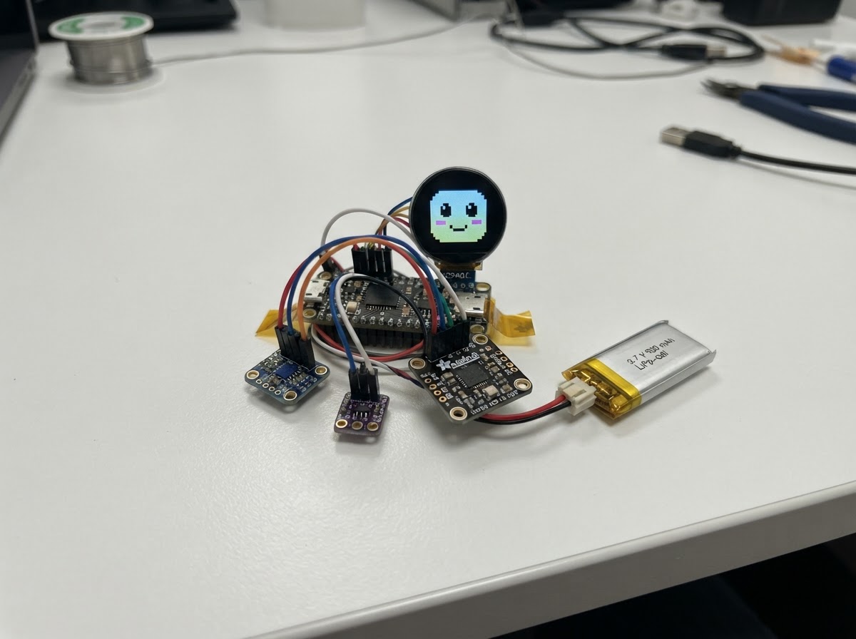
Starboy is a wearable digital pet companion that responds to the wearer's environment and activities. Built around an ESP32 microcontroller, it combines motion sensing from the QMI8658 IMU, environmental awareness through temperature and battery monitoring, and a vibrant 1.28-inch round display to show expressive animated faces that change mood based on acceleration, temperature, sound, and battery level.
This guide provides everything needed to assemble and program a fully functional Starboy device. Builders will receive a complete parts list, wiring diagram showing connections between the ESP32, sensors, and round TFT display, step-by-step assembly instructions for the 3D-printed case, and Arduino firmware that brings the pet to life with mood detection and animated expressions. The project runs on a compact 500 mAh LiPo battery, making it truly portable and wearable.
Wiring diagram

Gather all the parts
Assemble it in 10 steps
1. Print the first Starboy case
Print a two-piece case: a front face shell and a removable back cover. Make the outside about 85 mm tall, 70 mm wide, and 26 mm deep. In the front, make one centered 33 mm round opening for the lit part of the GC9A01 screen. Behind that opening, leave a 42 mm by 42 mm flat pocket at least 5 mm deep for the square screen circuit board. Make the case from PLA or PETG with 0.2 mm layers, three wall lines, and 15 to 20% infill. Print the front with its face pointing upward so the screen rim looks smooth.
- This is deliberately a roomy first case: it gives the wires and small sensor boards space instead of squeezing them.
- Use black, white, or silver filament for the shell; a black screen rim helps the round display look like a glossy robot eye.
- Do not use a metal-filled filament close to the antenna end of the XIAO board; metal can reduce wireless range.
- Do not permanently glue any electronics into the first print.
2. Make the openings before fitting electronics
On the back cover, make a USB-C opening about 10 mm wide and 5 mm tall where the XIAO USB-C socket will sit. Add a 4 mm round camera hole and a separate group of three 1 mm microphone holes. Add four or more small air holes near the temperature sensor position. Leave a 38 mm round recessed ring around the front screen opening for an optional clear plastic dome. The dome sits on the rim; it must not touch the LCD surface.
- Use a hand file or fine sandpaper to enlarge a printed opening gradually if it is tight.
- The camera needs its own clear hole; do not place it behind a dark screen window.
- Keep the microphone and temperature holes separate from the camera hole so dust or tape does not block all three.
- Do not make the temperature sensor compartment airtight; then it would mostly measure trapped warm air.
3. Gather the parts and keep the battery unplugged
Place the XIAO ESP32-S3 Sense, round screen, IMU, temperature sensor, fuel gauge, battery, printed front shell, and back cover on a clean table. You need a small soldering iron, electronics solder, thin flexible wire, wire cutters, small pieces of foam tape, and insulating tape or heat-shrink. Do not connect the LiPo battery yet. The camera and microphone are already part of the XIAO Sense board, so they do not need separate wires.
- Use red wire for 3.3 V power, black wire for GND, and two different colors for the shared sensor wires.
- Take a photo of each board’s printed pin labels before soldering.
- Do not plug in the LiPo battery while soldering or changing wires.
- This project uses 3.3 V power for the display and sensors. Never connect their power pins to 5 V.
4. Prepare and solder the small wires
Cut thin flexible wires long enough to reach around the inside edge of the case, then strip only 2 to 3 mm from each end. Put a tiny amount of solder on each bare wire end and each pad before joining them. Touch one wire to one pad with the iron just long enough for the solder to flow. Let it cool, then give the wire a gentle pull; it should stay fixed.
- Keep wires short, but leave a little slack so a board can be lifted out for repair.
- Practise joining two spare wires before soldering the small board pads.
- Do not hold the hot iron on a pad for more than a few seconds; a small pad can lift off the board.
- Look closely for solder blobs accidentally joining neighbouring XIAO pads.
5. Wire the round colour screen
Connect display VCC to XIAO 3.3 V (power), display BL or LED to XIAO 3.3 V (backlight power), display GND to XIAO GND (ground), display SCK to XIAO D8 / GPIO7 (screen timing), display MOSI to XIAO D10 / GPIO9 (screen picture data), display CS to XIAO D9 / GPIO8 (selects this screen), display DC to XIAO D3 / GPIO4 (tells the screen whether data is a command or picture), and display RST to XIAO D2 / GPIO3 (resets the screen).
- Keep the five screen signal wires under about 10 cm where possible.
- Before connecting power, use a multimeter to make sure screen VCC and GND are not accidentally joined.
- Do not connect display VCC or BL to 5 V or USB power; that can damage a 3.3 V display.
- Do not press on the round LCD surface or cover it with glue.
6. Make the shared sensor connections
Join the SDA pins on the IMU, temperature sensor, and fuel gauge together, then connect that joined wire group to XIAO D4 / GPIO5 (sensor data). Join the SCL pins on those same three boards together, then connect that joined wire group to XIAO D5 / GPIO6 (sensor timing). Connect each sensor VCC or VIN pin to XIAO 3.3 V (power), and each sensor GND pin to XIAO GND (ground).
- Make one small insulated SDA junction and one separate insulated SCL junction instead of piling several wires onto a tiny XIAO pad.
- Attach the IMU firmly to the shell so it feels Starboy being shaken instead of swinging on wires.
- Never join SDA to SCL; if they are swapped or joined, the sensors will not respond.
- Every sensor must share GND with the XIAO or its readings will be unreliable.
7. Place the boards in the printed front shell
Use thin foam tape, not permanent glue, to place the round screen flat in its 42 mm square front pocket. Center its lit circle behind the 33 mm face opening. Put the XIAO board behind and to one side of the screen, with its camera aligned to the camera hole and its USB-C socket aligned to the back opening. Tape the IMU firmly to the main shell. Put the temperature sensor beside the small air holes and away from the warm screen and XIAO. Put the fuel gauge and battery in the roomy rear area, with the battery lying flat.
- Route wires around the outer edge of the cavity so they do not sit directly behind the display.
- Use a small folded paper spacer behind the screen if it sits too deep in the first print.
- Do not bend, puncture, crush, or screw through the soft battery pouch.
- Do not block the camera, microphone holes, USB-C socket, or temperature air holes with tape or wires.
8. Check the battery connection carefully
The 3.7 V LiPo’s listed JST-SH plug may not fit the XIAO socket or the MAX17048 fuel-gauge board. Compare the plug shape and the positive/negative wire order before connecting it. Use a multimeter to confirm the red battery wire is positive and black wire is negative. Only use a correctly keyed adapter or harness that keeps positive connected to positive and negative connected to negative. The fuel gauge’s BAT connection goes to battery positive as shown in the project diagram; its GND shares the battery negative/ground connection.
- Keep enough loose wire to unplug the battery for servicing without pulling on a soldered joint.
- Secure the battery only after its connector and polarity are confirmed.
- Never force a battery plug into a socket.
- Never solder directly to a LiPo pouch, its metal tabs, or wires next to the pouch.
- Disconnect immediately if the battery, wire, or board becomes hot, swells, or smells unusual.
9. Test with USB power before closing the case
Leave the LiPo unplugged. Inspect every solder joint under good light. If you have a multimeter, check that the XIAO 3.3 V and GND pads are not shorted together. Plug the XIAO into USB-C, then use Schematik’s Deploy button to build and flash the project. Confirm that the round screen lights and that Starboy responds to sound, movement, and room temperature while the shell is still open.
- If the screen stays black, unplug USB and recheck the eight screen wires in Step 5 one at a time.
- If all sensors fail, unplug USB and recheck the shared SDA, SCL, 3.3 V, and GND junctions in Step 6.
- Do not move wires while USB or battery power is connected.
- Disconnect power immediately if any board becomes unexpectedly hot.
10. Fit the clear dome and close Starboy
After the USB test works and the battery connection has been verified, unplug USB, connect the LiPo, and watch the open project for one or two minutes. Nothing should get hot. Place an optional clear 36 to 38 mm acrylic or polycarbonate dome in the recessed front ring, using a very small bead of clear adhesive only on the outer rim. Do not let adhesive touch the screen. Close the back cover with small screws or a removable snap fit, then check that the display is centered and the USB, camera, microphone, and air openings remain clear.
- A smoked-clear dome gives the face a glossy appearance while keeping the colored eyes visible.
- Keep the first case easy to reopen until Starboy has been used for several days.
- Never close the case if the battery wiring is uncertain or anything becomes warm.
- Never charge a damaged, swollen, or warm LiPo battery, and do not leave it charging unattended.
Review all connections
1. Connections between "imu" and "ESP32"
2. Connections between "temperature" and "ESP32"
3. Connections between "fuel_gauge" and "ESP32"
4. Connections between "lipo" and "ESP32"
5. Connections between "face_tft" and "ESP32"
Deploy the firmware
#include <Arduino.h>
#include <Wire.h>
#include <SPI.h>
#include <Adafruit_GFX.h>
#include <Adafruit_GC9A01A.h>
#include <Adafruit_TMP117.h>
#include <Adafruit_MAX1704X.h>
#include <esp_camera.h>
#include <driver/i2s.h>


// Hoisted type definitions
enum Mood { HAPPY, ANXIOUS, COLD, DIZZY, SAD, BATTERY };


// Forward declarations
bool i2cRead(uint8_t address, uint8_t reg, uint8_t *data, size_t count);
bool beginQmi8658();
float readAccelerationG();
void configureMicrophone();
float readSoundLevel();
bool initCamera();
bool cameraIsCovered();
bool cameraSeesThumbsUpCue();
void drawEye(int x, int y, uint16_t pupilColor, bool crossed);
void drawFace(Mood current);
void updateMood();

constexpr int I2C_SDA = 5;
constexpr int I2C_SCL = 6;
constexpr int TFT_SCK = 7;
constexpr int TFT_MOSI = 9;
constexpr int TFT_CS = 8;
constexpr int TFT_DC = 4;
constexpr int TFT_RST = 3;
constexpr int MIC_CLK = 42;
constexpr int MIC_DATA = 41;
constexpr uint8_t QMI_ADDRESS = 0x6A;
constexpr uint32_t SENSOR_INTERVAL_MS = 250;


Adafruit_GC9A01A display(TFT_CS, TFT_DC, TFT_RST);
Adafruit_TMP117 tempSensor;
Adafruit_MAX17048 fuelGauge;
bool hasTemp = false;
bool hasFuel = false;
bool hasImu = false;
bool hasCamera = false;
Mood mood = HAPPY;
Mood lastDrawnMood = SAD;
float temperatureC = 22.0f;
float batteryPct = -1.0f;
float soundLevel = 0.0f;
float accelerationG = 1.0f;
int lastDrawnBattery = -999;
uint32_t lastSensor = 0;
uint32_t moodUntil = 0;

bool i2cRead(uint8_t address, uint8_t reg, uint8_t *data, size_t count) {
  Wire.beginTransmission(address);
  Wire.write(reg);
  if (Wire.endTransmission(false) != 0) return false;
  if (Wire.requestFrom((int)address, (int)count) != (int)count) return false;
  for (size_t i = 0; i < count; ++i) data[i] = Wire.read();
  return true;
}

bool beginQmi8658() {
  Wire.beginTransmission(QMI_ADDRESS);
  return Wire.endTransmission() == 0;
}

float readAccelerationG() {
  uint8_t raw[6];
  if (!i2cRead(QMI_ADDRESS, 0x35, raw, sizeof(raw))) return accelerationG;
  int16_t x = (int16_t)((raw[1] << 8) | raw[0]);
  int16_t y = (int16_t)((raw[3] << 8) | raw[2]);
  int16_t z = (int16_t)((raw[5] << 8) | raw[4]);
  const float scale = 4096.0f;
  float xf = x / scale, yf = y / scale, zf = z / scale;
  return sqrtf(xf * xf + yf * yf + zf * zf);
}

void configureMicrophone() {
  i2s_config_t config = {};
  config.mode = (i2s_mode_t)(I2S_MODE_MASTER | I2S_MODE_RX | I2S_MODE_PDM);
  config.sample_rate = 16000;
  config.bits_per_sample = I2S_BITS_PER_SAMPLE_16BIT;
  config.channel_format = I2S_CHANNEL_FMT_ONLY_LEFT;
  config.communication_format = I2S_COMM_FORMAT_I2S;
  config.intr_alloc_flags = ESP_INTR_FLAG_LEVEL1;
  config.dma_buf_count = 4;
  config.dma_buf_len = 128;
  i2s_driver_install(I2S_NUM_0, &config, 0, nullptr);
  i2s_pin_config_t pins = {};
  pins.bck_io_num = I2S_PIN_NO_CHANGE;
  pins.ws_io_num = MIC_CLK;
  pins.data_out_num = I2S_PIN_NO_CHANGE;
  pins.data_in_num = MIC_DATA;
  i2s_set_pin(I2S_NUM_0, &pins);
}

float readSoundLevel() {
  int16_t samples[128];
  size_t bytesRead = 0;
  if (i2s_read(I2S_NUM_0, samples, sizeof(samples), &bytesRead, 20 / portTICK_PERIOD_MS) != ESP_OK || bytesRead == 0) return soundLevel;
  int count = bytesRead / sizeof(int16_t);
  double sum = 0;
  for (int i = 0; i < count; ++i) sum += (double)samples[i] * samples[i];
  return sqrt(sum / count) / 32768.0f;
}

bool initCamera() {
  camera_config_t config = {};
  config.ledc_channel = LEDC_CHANNEL_0;
  config.ledc_timer = LEDC_TIMER_0;
  config.pin_d0 = 15; config.pin_d1 = 17; config.pin_d2 = 18; config.pin_d3 = 16;
  config.pin_d4 = 14; config.pin_d5 = 12; config.pin_d6 = 11; config.pin_d7 = 48;
  config.pin_xclk = 10; config.pin_pclk = 13; config.pin_vsync = 38; config.pin_href = 47;
  config.pin_sscb_sda = 40; config.pin_sscb_scl = 39;
  config.pin_pwdn = -1; config.pin_reset = -1;
  config.xclk_freq_hz = 20000000;
  config.pixel_format = PIXFORMAT_GRAYSCALE;
  config.frame_size = FRAMESIZE_QQVGA;
  config.jpeg_quality = 12;
  config.fb_count = 1;
  config.grab_mode = CAMERA_GRAB_LATEST;
  return esp_camera_init(&config) == ESP_OK;
}

bool cameraIsCovered() {
  if (!hasCamera) return false;
  camera_fb_t *frame = esp_camera_fb_get();
  if (!frame) return false;
  uint32_t total = 0;
  for (size_t i = 0; i < frame->len; i += 16) total += frame->buf[i];
  uint8_t average = total / ((frame->len + 15) / 16);
  esp_camera_fb_return(frame);
  return average < 18;
}

bool cameraSeesThumbsUpCue() {
  if (!hasCamera) return false;
  camera_fb_t *frame = esp_camera_fb_get();
  if (!frame) return false;
  int topBright = 0, lowerBright = 0;
  for (int y = 0; y < frame->height; y += 4) {
    for (int x = frame->width / 3; x < (frame->width * 2) / 3; x += 4) {
      if (frame->buf[y * frame->width + x] > 140) {
        if (y < frame->height / 2) ++topBright; else ++lowerBright;
      }
    }
  }
  esp_camera_fb_return(frame);
  return topBright > 20 && topBright > lowerBright * 1.4f;
}

void drawEye(int x, int y, uint16_t pupilColor, bool crossed) {
  display.fillEllipse(x, y, 45, 59, GC9A01A_WHITE);
  if (crossed) {
    display.drawLine(x - 15, y - 16, x + 15, y + 16, GC9A01A_BLACK);
    display.drawLine(x + 15, y - 16, x - 15, y + 16, GC9A01A_BLACK);
  } else {
    display.fillEllipse(x, y + 3, 16, 23, pupilColor);
    display.fillCircle(x - 5, y - 5, 4, GC9A01A_WHITE);
  }
}

void drawFace(Mood current) {
  const uint16_t faceBg = display.color565(25, 24, 38);
  const uint16_t blue = display.color565(54, 75, 255);
  const uint16_t anxiousBlue = display.color565(145, 180, 255);
  const uint16_t coldBlue = display.color565(105, 225, 255);
  display.fillScreen(GC9A01A_BLACK);
  display.fillCircle(120, 120, 116, faceBg);
  int leftY = 116, rightY = 116;
  if (current == ANXIOUS) { leftY = 106; rightY = 106; }
  if (current == SAD) { leftY = 127; rightY = 127; }
  if (current == COLD) { leftY = 120; rightY = 120; }
  bool crossed = current == DIZZY;
  uint16_t pupil = current == COLD ? coldBlue : (current == ANXIOUS ? anxiousBlue : blue);
  drawEye(76, leftY, pupil, crossed);
  drawEye(164, rightY, pupil, crossed);
  if (current == HAPPY || current == BATTERY) {
    display.drawArc(120, 166, 28, 18, 15, 165, GC9A01A_WHITE);
  } else if (current == SAD) {
    display.drawArc(120, 187, 28, 18, 195, 345, GC9A01A_WHITE);
  } else if (current == ANXIOUS) {
    display.fillCircle(120, 172, 9, GC9A01A_WHITE);
  } else if (current == COLD) {
    display.drawLine(99, 167, 108, 174, coldBlue);
    display.drawLine(108, 174, 117, 167, coldBlue);
    display.drawLine(123, 167, 132, 174, coldBlue);
    display.drawLine(132, 174, 141, 167, coldBlue);
  }
  display.setTextColor(GC9A01A_WHITE);
  display.setTextSize(2);
  if (current == BATTERY) {
    display.setCursor(66, 20);
    display.print("BAT ");
    display.print(batteryPct < 0 ? 0 : (int)batteryPct);
    display.print('%');
  } else if (current == ANXIOUS) { display.setCursor(62, 20); display.print("LOUD"); }
  else if (current == COLD) { display.setCursor(70, 20); display.print("BRR"); }
  else if (current == DIZZY) { display.setCursor(58, 20); display.print("DIZZY"); }
  else if (current == SAD) { display.setCursor(72, 20); display.print("oh..."); }
  else { display.setCursor(53, 20); display.print("starboy"); }
}

void updateMood() {
  if (cameraIsCovered()) { mood = SAD; moodUntil = millis() + 5000; return; }
  if (cameraSeesThumbsUpCue()) { mood = BATTERY; moodUntil = millis() + 5000; return; }
  if (accelerationG > 2.4f) { mood = DIZZY; moodUntil = millis() + 4000; return; }
  if (temperatureC < 15.0f) { mood = COLD; moodUntil = millis() + 2500; return; }
  if (soundLevel > 0.075f) { mood = ANXIOUS; moodUntil = millis() + 2500; return; }
  if (millis() > moodUntil) mood = HAPPY;
}

void setup() {
  Wire.begin(I2C_SDA, I2C_SCL);
  Wire.setClock(400000);
  SPI.begin(TFT_SCK, -1, TFT_MOSI, TFT_CS);
  display.begin();
  display.setRotation(0);
  hasTemp = tempSensor.begin();
  hasFuel = fuelGauge.begin();
  hasImu = beginQmi8658();
  configureMicrophone();
  hasCamera = initCamera();
  drawFace(HAPPY);
  lastDrawnMood = HAPPY;
}

void loop() {
  uint32_t now = millis();
  if (now - lastSensor < SENSOR_INTERVAL_MS) return;
  lastSensor = now;
  if (hasTemp) temperatureC = tempSensor.readTempC();
  if (hasFuel) batteryPct = fuelGauge.cellPercent();
  if (hasImu) accelerationG = readAccelerationG();
  soundLevel = readSoundLevel();
  updateMood();
  int displayedBattery = batteryPct < 0 ? -1 : (int)batteryPct;
  if (mood != lastDrawnMood || (mood == BATTERY && displayedBattery != lastDrawnBattery)) {
    drawFace(mood);
    lastDrawnMood = mood;
    lastDrawnBattery = displayedBattery;
  }
}
Remix this project
Make it yours in one click
Open a full copy of this project in your own Schematik workspace — diagram, code, parts, and assembly steps included. Swap the sensor, add features, or redesign the whole thing with AI. The author's original stays untouched.