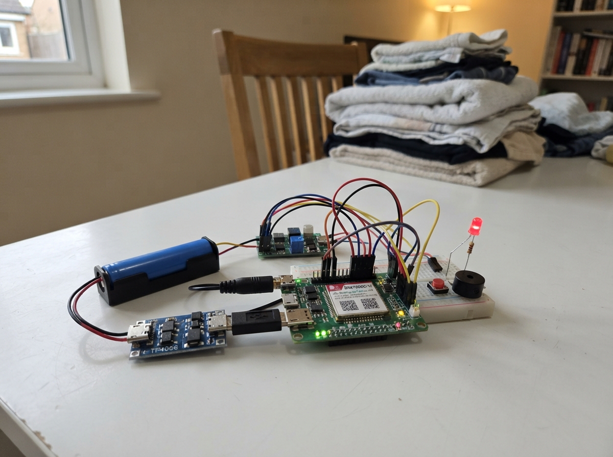
This wearable distress alarm uses an ESP32 microcontroller and 4G LTE modem to send emergency SMS alerts when a button is pressed. The device runs on a rechargeable 18650 battery with integrated charging and protection, boosted to 5V to power all electronics. A piezo buzzer and LED provide immediate audio and visual feedback while the SMS is being transmitted to a pre-configured helper's phone number.
The guide provides a complete parts list, wiring diagram, and step-by-step assembly instructions for building a portable emergency device. Firmware code is included and ready to customize with a recipient phone number. The project covers battery management, 4G modem initialization, button debouncing, and SMS transmission logic, making it suitable for personal safety applications in remote areas or situations where voice calls may not be possible.
Wiring diagram
Gather all the parts
Assemble it in 6 steps
1. Gather the right hardware
Buy an ESP32 DevKit v1, a SIM7600G-H UART development board that explicitly states it has a SIM-card holder, 5 V input, and 3.3 V TTL UART pins, its LTE antenna, a genuine Samsung INR18650-30Q cell, a TP4056 charger module with protection, a 30 W adjustable boost converter, a momentary push button, passive piezo buzzer, red LED, 220 Ω resistor, small slide switch, USB charging lead, insulated wire, and a non-metal project box. Also get an activated South African nano-SIM with SMS airtime.
- DIYElectronics lists a SIM7600G-H board; Netram lists TP4056 chargers; Electronic Pro lists a 30 W boost module; Robotics.org.za and NDE3D list related battery power boards. Check the actual item description before paying.
- Choose a SIM7600G-H board with an external antenna connector and a clearly labelled 5V, GND, TXD, RXD, and PWRKEY header.
- Do not buy a 2G-only SIM800L for this build: it is not the planned South African 4G design.
- Do not use damaged, unbranded, or loose lithium-ion cells; a short circuit can cause a fire.
2. Make the protected battery section
With all power disconnected, place the 18650 cell in a suitable single-cell holder or connect it to the TP4056 only through its intended B+ and B- pads: cell positive to B+ (battery positive), and cell negative to B- (battery negative). Connect the TP4056 OUT+ to the centre COM pin of the slide switch (switched power), and connect TP4056 OUT- to boost_1 VIN- (ground). Connect slide-switch pin A to boost_1 VIN+ (switched battery power). Leave slide-switch pin B unused.
- Keep the battery wires short and use thicker wire than the small signal wires.
- The TP4056 USB input is for charging only; do not try to power the 4G board straight from its tiny USB connector.
- Reversed B+ and B- can destroy the charger or heat the battery.
- Never solder directly to an 18650 cell; use a holder or a cell with factory-fitted leads.
3. Set the 5 V output before connecting electronics
Turn the slide switch on with no ESP32 or SIM7600 connected. Use a multimeter between boost_1 VOUT+ and VOUT- and turn the small adjustment screw until it reads 5.0 V. Turn the switch off. Connect VOUT+ to the ESP32 5V/VIN pin and to SIM7600 5V (power). Connect VOUT- to an ESP32 GND pin and SIM7600 GND (ground).
- Put the SIM7600 close to the boost converter and use short, thicker positive and ground wires so radio transmit bursts do not cause a reset.
- Fit the supplied cellular antenna before turning on the SIM7600.
- More than 5 V can damage the ESP32 or SIM7600 board.
- Never run the SIM7600 without its antenna attached; its radio can be damaged or work very poorly.
4. Wire the button, sounder, and light
Connect panic_button GND to ESP32 GND (ground) and panic_button SIGNAL to GPIO32 (signal). Connect buzzer_1 SIG to GPIO25 (alarm tone) and buzzer_1 GND to ESP32 GND (ground). Put one resistor lead, led_resistor P1, into GPIO26 (light signal), and connect its other lead, P2, to the long LED leg, status_led ANODE (current-limited light positive). Connect the LED short leg, status_led GND, to ESP32 GND (ground).
- The LED long leg is positive; the flat side beside the short leg marks the negative side.
- Mount the button where it cannot be pressed accidentally inside a pocket; a recessed opening or flip cover helps.
- Do not connect the LED directly to GPIO26; the 220 Ω resistor limits current and protects both the LED and the ESP32.
5. Wire the cellular data leads
Connect SIM7600 TXD to ESP32 GPIO16 (data from the cellular board), SIM7600 RXD to ESP32 GPIO17 (data to the cellular board), and SIM7600 PWRKEY to ESP32 GPIO27 (radio start signal). Keep the shared ground from step 3 connected.
- TX and RX deliberately cross: a pin labelled TX sends data, so it goes to the other board's RX pin.
- Only use a SIM7600 development board whose TXD and RXD are labelled 3.3 V TTL compatible; do not connect an unlevel-shifted 5 V serial output to the ESP32.
- Do not swap 5V and GND; swapped power can permanently damage the cellular board.
6. Fit, test, and close the alarm
Insert the activated nano-SIM into the SIM7600 slot while power is off. Put the antenna where it is not pressed against the battery, then switch on and use a temporary open enclosure for the first test. The device needs the recipient phone number set in its firmware before its first real test. Once it sends a test text and the buzzer works, secure every board with standoffs or foam tape and close the non-metal enclosure without pinching wires.
- Test with a real helper contact in a place with mobile signal. Hold the button for two seconds; a steady light means the modem accepted the text, while three flashes means it did not.
- Charge only while supervised, on a non-flammable surface.
- This is a personal alert device, not a replacement for calling emergency services. Mobile coverage, SIM activation, airtime, battery charge, and the recipient number all affect whether a text arrives.
Review all connections
1. Connections between "cell_1" and "ESP32"
2. Connections between "charger_1" and "ESP32"
3. Connections between "power_switch" and "ESP32"
4. Connections between "boost_1" and "ESP32"
5. Connections between "sim7600_1" and "ESP32"
6. Connections between "panic_button" and "ESP32"
7. Connections between "buzzer_1" and "ESP32"
8. Connections between "led_resistor" and "ESP32"
9. Connections between "status_led" and "ESP32"
Deploy the firmware
#include <Arduino.h>

constexpr int MODEM_RX_PIN = 16;
constexpr int MODEM_TX_PIN = 17;
constexpr int MODEM_PWRKEY_PIN = 27;
constexpr int BUTTON_PIN = 32;
constexpr int BUZZER_PIN = 25;
constexpr int LED_PIN = 26;

// Replace this with the helper's number before deployment, e.g. "+27821234567".
const char RECIPIENT_NUMBER[] = "+27XXXXXXXXX";
const char ALERT_TEXT[] = "DISTRESS ALERT: I need help. Please call me and check on me.";

HardwareSerial modem(2);

bool alarmActive = false;
bool buttonWasDown = false;
unsigned long buttonDownAt = 0;
unsigned long lastAlarmToggleAt = 0;
bool toneOn = false;

void setAlarmSound(bool enabled) {
  if (enabled) {
    ledcAttach(BUZZER_PIN, 4000, 8);
    ledcWriteTone(BUZZER_PIN, 4000);
  } else {
    ledcWriteTone(BUZZER_PIN, 0);
    ledcDetach(BUZZER_PIN);
    digitalWrite(BUZZER_PIN, LOW);
  }
}

bool waitForModem(const char *expected, unsigned long timeoutMs) {
  String response;
  unsigned long startedAt = millis();
  while (millis() - startedAt < timeoutMs) {
    while (modem.available()) {
      char c = static_cast<char>(modem.read());
      response += c;
      if (response.indexOf(expected) >= 0) {
        return true;
      }
      if (response.indexOf("ERROR") >= 0) {
        return false;
      }
    }
    delay(10);
  }
  return false;
}

bool sendCommand(const char *command, const char *expected, unsigned long timeoutMs) {
  while (modem.available()) {
    modem.read();
  }
  modem.println(command);
  return waitForModem(expected, timeoutMs);
}

bool sendSms() {
  if (String(RECIPIENT_NUMBER).indexOf('X') >= 0) {
    return false;
  }

  // Most SIM7600 development boards start after this active-low one-second pulse.
  digitalWrite(MODEM_PWRKEY_PIN, LOW);
  delay(1100);
  digitalWrite(MODEM_PWRKEY_PIN, HIGH);
  delay(3500);

  if (!sendCommand("AT", "OK", 5000)) return false;
  if (!sendCommand("AT+CMGF=1", "OK", 3000)) return false;

  while (modem.available()) {
    modem.read();
  }
  modem.print("AT+CMGS=\"");
  modem.print(RECIPIENT_NUMBER);
  modem.println("\"");
  if (!waitForModem(">", 5000)) return false;

  modem.print(ALERT_TEXT);
  modem.write(26); // Ctrl+Z sends the SMS.
  return waitForModem("+CMGS:", 30000);
}

void startDistressAlert() {
  alarmActive = true;
  digitalWrite(LED_PIN, HIGH);
  setAlarmSound(true);
  bool sent = sendSms();

  // A steady LED means the modem accepted the SMS. Three quick flashes means it did not.
  if (sent) {
    digitalWrite(LED_PIN, HIGH);
  } else {
    for (int i = 0; i < 3; ++i) {
      digitalWrite(LED_PIN, LOW);
      delay(180);
      digitalWrite(LED_PIN, HIGH);
      delay(180);
    }
  }
}

void setup() {
  pinMode(BUTTON_PIN, INPUT_PULLUP);
  pinMode(LED_PIN, OUTPUT);
  pinMode(BUZZER_PIN, OUTPUT);
  pinMode(MODEM_PWRKEY_PIN, OUTPUT);
  digitalWrite(LED_PIN, LOW);
  digitalWrite(BUZZER_PIN, LOW);
  digitalWrite(MODEM_PWRKEY_PIN, HIGH);
  modem.begin(115200, SERIAL_8N1, MODEM_RX_PIN, MODEM_TX_PIN);
}

void loop() {
  bool buttonDown = digitalRead(BUTTON_PIN) == LOW;
  unsigned long now = millis();

  if (!alarmActive) {
    if (buttonDown && !buttonWasDown) {
      buttonDownAt = now;
    }
    if (!buttonDown) {
      buttonDownAt = 0;
    }
    if (buttonDown && buttonDownAt != 0 && now - buttonDownAt >= 2000) {
      startDistressAlert();
    }
  }
  buttonWasDown = buttonDown;

  if (alarmActive && now - lastAlarmToggleAt >= 500) {
    lastAlarmToggleAt = now;
    toneOn = !toneOn;
    setAlarmSound(toneOn);
  }
  delay(10);
}
Remix this project
Make it yours in one click
Open a full copy of this project in your own Schematik workspace, diagram, code, parts, and assembly steps included. Swap the sensor, add features, or redesign the whole thing with AI. The author's original stays untouched.