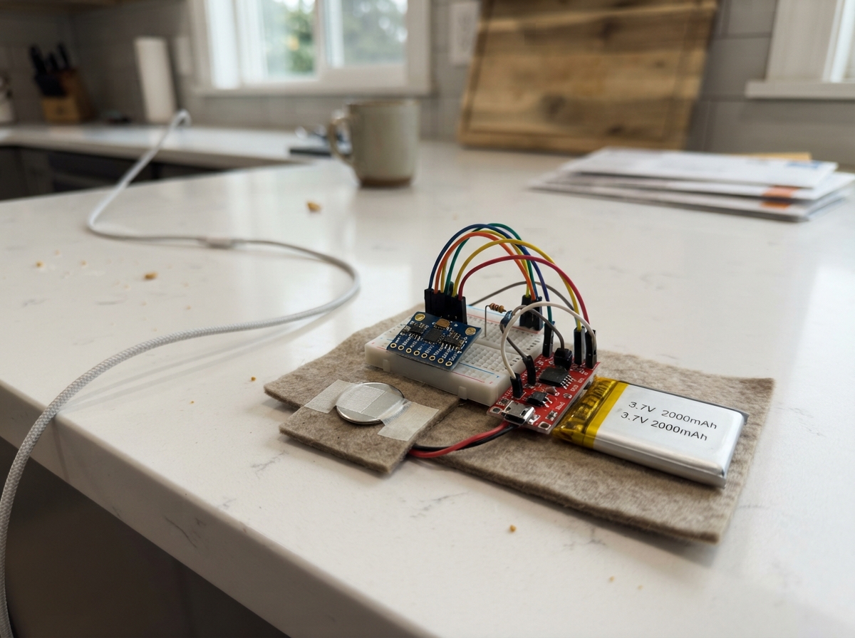
This wearable device detects fetal movements by combining a 6-axis motion sensor (MPU6050) with a piezo disc vibration detector worn against the skin. The ESP32 processes both acceleration and gyroscope data in real time, filtering out noise and distinguishing genuine fetal kicks from maternal movement using adaptive thresholds. A rechargeable lithium battery powers the system for extended monitoring sessions.
The guide provides a complete wiring diagram, parts list with sourcing details, and step-by-step assembly instructions for building the detection pod and battery management circuit. Firmware is included with calibration routines and event logging, allowing the device to record movement patterns over time. Builders will learn how to integrate motion sensing with piezo feedback, implement power management with the TP4056 charger, and tune detection sensitivity for reliable operation.
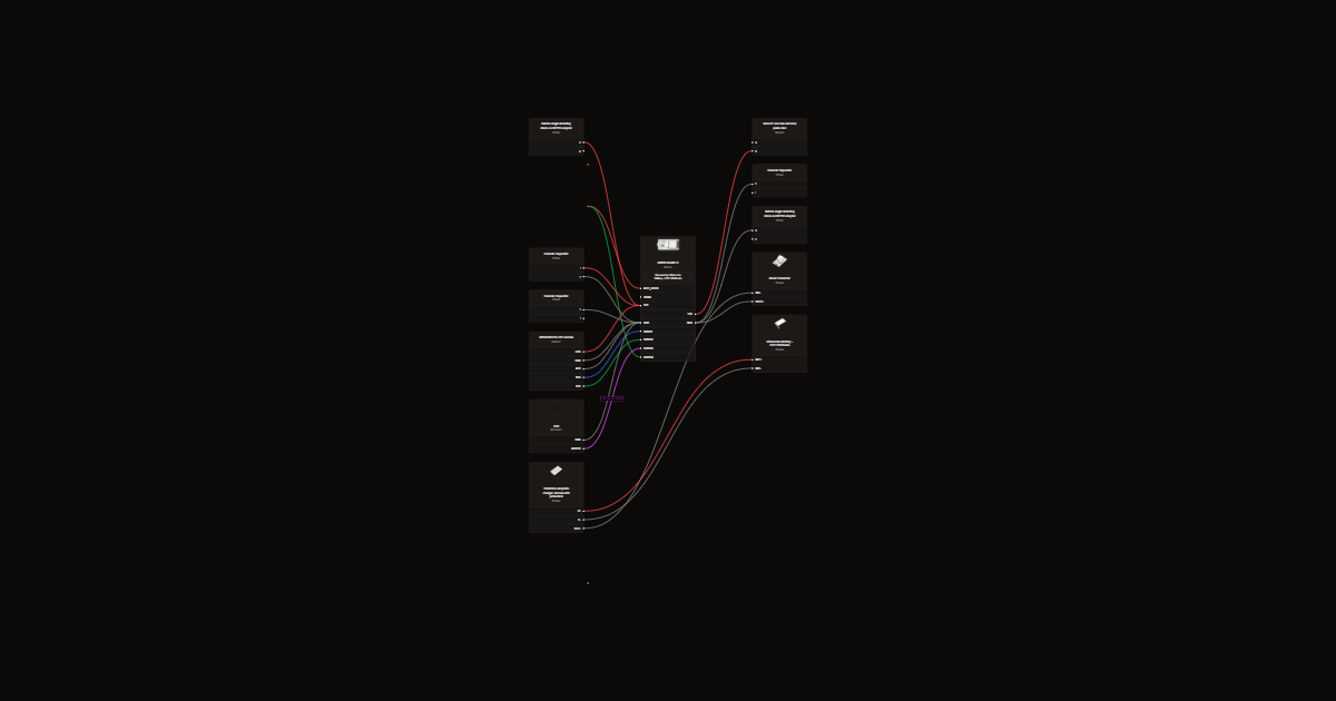
Wiring diagram
Gather all the parts
Assemble it in 9 steps
1. Prepare the unpowered bench circuit
Use an 830-point breadboard for sensors only and insulated flexible wires. Keep the battery disconnected. Check split breadboard rails with a multimeter. Use a USB data cable for initial ESP32 operation, with the boost-to-VIN JST link physically disconnected.
- Not a medical device. Do not use counts to assess fetal wellbeing. Do not wear while connected to USB or charging.
2. Wire the motion sensor
GY-521 VCC to 3V3, GND and AD0 to GND, SDA to GPIO21 (data), SCL to GPIO22 (clock). Leave INT, XDA and XCL open. Keep leads short.
3. Create the three separate piezo junctions
Top 100k resistor from 3V3 to VBIAS; bottom 100k from VBIAS to GND. Put 1uF from VBIAS to GND. Piezo A to VBIAS, B to PZ_NODE. Place 1M directly across A and B. Put third 100k from PZ_NODE to ADC_NODE; connect ADC_NODE to GPIO34.
4. Protect and stabilise the input
Use two single BAT54 diodes on breadboard adapters: pin1 anode and pin3 cathode; pin2 unconnected. Lower diode anode to GND, cathode to ADC_NODE. Upper diode anode to ADC_NODE, cathode to 3V3. Put 10nF from ADC_NODE to GND and 100nF from 3V3 to GND nearby. Verify adapters with diode mode.
- Rail clamps are not a guarantee against arbitrary piezo overvoltage. Avoid hard impacts and disconnect piezo when unpowered; do not flex or strike the disc.
5. Connect the operating indicator
GPIO25 to 330 ohm resistor to LED anode (long leg). LED cathode (short leg/flat side) to GND.
6. Prepare the battery assembly
Select protected 3.7V 2000mAh LiPo rated for at least 500mA charging and 1A discharge. Buy protected six-pad TP4056 module preset to 500mA (2.4k onboard PROG resistor), not standard 1A. Battery plus to B+, minus to B-. OUT+ to switch COM, switch A to boost VIN+, switch B open. OUT- to boost VIN-. Do not join B- to OUT- externally. Use a slide switch rated at least 1A DC.
- Charge off-body with switch OFF; TP4056 has no load sharing. Never charge unattended or charge a swollen/damaged cell. Check JST polarity with a meter, not wire colours alone.
7. Adjust and connect the boost converter
With ESP32 disconnected, turn switch on and measure boost VOUT+ to VOUT-. Adjust to 5.00V. Switch off. VOUT- to ESP32 GND; VOUT+ through removable two-pin JST power link to VIN/5V. Use soldered power connections, not loose breadboard contacts.
- Disconnect the whole boost-to-ESP32 power link before plugging USB into ESP32. Switch OFF alone does not prevent USB back-feed into the boost. Never connect battery power and ESP32 USB together.
8. Mount the wearable pod
After bench verification, solder sensor conditioning onto perfboard. Mount MPU6050 rigidly beside the piezo in a front belt pod. Support piezo rim with light contact through a thin insulating cover; avoid squeezing ceramic or immobilising it with thick glue. Use short flexible twisted sensor leads and keyed detachable JSTs. Put ESP32 and power modules on the outer side, boost farthest from ADC wiring, antenna free of metal. Place protected battery in a separate padded outer pocket away from skin, pressure, bends and heat. Provide insulated standoffs, strain relief and access to switch and charger. Use a comfortable loose elastic belt, never abdominal compression.
9. Reference schematic and bench checks
# Wearable experimental movement belt No simulator, actuator, motor or second microcontroller is included. ## Pin assignments and separate wiring diagrams | ESP32 pin | Wire/job | |---|---| |3V3|GY-521 VCC, Rtop supply, upper diode cathode, C_supply| |GND|GY-521 GND/AD0, bias return, lower diode anode, capacitors, LED cathode, boost VOUT-| |GPIO21|GY-521 SDA, I2C data| |GPIO22|GY-521 SCL, I2C clock| |GPIO34|ADC_NODE, analog input only, ADC1| |GPIO25|330 ohm resistor then LED anode| |VIN/5V|Boost 5.00V ONLY when ESP32 USB absent| MPU diagram: VCC--3V3; GND--GND; AD0--GND; SDA--21; SCL--22. INT, XDA, XCL are open. Use GY-521, not the catalog's DFRobot module. ## Complete piezo schematic ``` 3V3 -- Rtop 100k --+-- VBIAS -- Rbottom 100k -- GND | +-- C_bias 1uF -- GND | +-- A [bare piezo disc] B --+-- PZ_NODE | | +-------- Rbleed 1M --------+ | Rseries 100k | ADC_NODE -------- GPIO34 | +-- C_adc 10nF -- GND | GND -- anode Dlow BAT54 cathode ---------------+ | +-- anode Dhigh BAT54 cathode -- 3V3 3V3 -- C_supply 100nF -- GND ``` Single BAT54: SOT23 pin1=A, pin3=K, pin2=NC; use adapters. Do NOT substitute BAT54A/C/S without a new pin map. 10nF added at ADC_NODE provides charge storage for the ESP32 ADC and some analog filtering; 100k and 10nF alone have nominal 159Hz corner, actual response also depends on piezo/bias impedance. It is not a complete 50Hz anti-alias filter: 100Hz acquisition can miss fast vibrations. **Safety limitation:** the specified Schottky clamps limit approximately to -Vf and 3.3V+Vf, NOT exactly 0..3.3V. Datasheet BAT54 Vf is up to 240mV at 0.1mA and 320mV at 1mA. Thus arbitrary impacts cannot be guaranteed within ESP32 absolute limits by this circuit. Rseries limits current; gentle belt movement only. Disconnect piezo when unpowered to avoid feeding the 3.3V rail. A production design needs characterised transducer maximum voltage, overvoltage-rated analog front end and verified input limits across temperature. No protection against arbitrary abuse is claimed. ## Actual power connections ``` Protected 1S LiPo BAT+ ---------------- TP4056 B+ Protected 1S LiPo BAT- ---------------- TP4056 B- 5V charging USB positive -------------- TP4056 IN+ Charging USB negative ---------------- TP4056 IN- TP4056 OUT+ -- switch COM / A --------- MT3608 VIN+ TP4056 OUT- --------------------------- MT3608 VIN- MT3608 VOUT+ -- removable JST link ---- ESP32 VIN/5V MT3608 VOUT- -- removable JST link ---- ESP32 GND (common circuit ground) ``` Do not bypass negative-side protection by wiring B- directly to OUT-/circuit GND. Switch B unused. Charger USB is its own module port, NOT ESP32 USB. Protected TP4056 must have OUT+/OUT-, DW01 and protection MOSFETs. Select a module factory configured to 500mA with 2.4k PROG resistor; do not add a second resistor in parallel. Check battery maker allows 500mA charge and >=1A discharge. The 2000mAh protected pack is selected. No load sharing: turn OFF to charge. Do not operate during charging. Remove from body and charge on a nonflammable surface. Estimated runtime about 5 hours, depends strongly on board/converter and cell; not measured. USB bench/programming mode: unplug boost-to-ESP32 JST link, then connect ESP32 USB data cable. Battery mode: unplug ESP32 USB first, reconnect power link and switch on. No simultaneous laptop logging on ordinary USB while battery-powered in this design. A hardware USB power mux/isolation redesign is needed for that. The ON/OFF switch by itself is not USB isolation. ## LED diagram GPIO25 -- 330 ohm -- LED anode; LED cathode -- GND. Slow blink=calibration, solid=acquiring, fast blink=startup MPU fault; LED off during read error. ## Bill of materials - 1 ESP32 DevKit V1 ESP32-WROOM-32. - 1 GY-521 MPU6050 module, 3.3V I2C. - 1 bare 27mm two-electrode piezo disc with leads. - 3 resistors 100kohm, 1%; 1 resistor 1Mohm, 1%; 1 resistor 330ohm; all 0.25W. - 2 single BAT54 Schottky diodes, each on SOT23-to-through-hole adapter. - 1 each ceramic capacitor: 1uF, 10nF, 100nF, rated >=16V. - 1 green/red low-current LED. - 1 protected 3.7V 2000mAh LiPo (4.2V full). - 1 protected six-pad TP4056 module, 500mA preset, USB charging connector. - 1 MT3608 boost module, adjusted to 5.00V; allow >=500mA output at low cell voltage, not advertised switch-current rating. - 1 slide switch rated >=1A DC. - 1 830-point breadboard; 1 small perfboard; header sockets as needed. - Keyed JST connector pairs: battery 2-pin, removable power link 2-pin, piezo 2-pin, MPU 4-pin (3V3,GND,SDA,SCL); AD0 grounded locally. Battery connector may already be supplied. - Flexible insulated stranded wire, 22-24AWG power and 26-28AWG sensors; jumper wires for bench. - 1 ESP32 USB data cable and separate charger USB cable/5V supply. - Insulating pod, elastic belt, padded battery pocket, heat-shrink and strain-relief materials. Multimeter required for polarity and boost adjustment. ## Firmware and testing Complete Arduino-framework firmware is src/main.cpp. Schematik Deploy installs/compiles/flashes; no external libraries needed. Register reads verify WHO_AM_I=0x68, use +/-2g and +/-250deg/s, digital low-pass setting 4 and sample divider 9. Readout is SI units plus 12-bit ADC counts, averaged over eight conversions at each 10ms sample. 1. Build breadboard sensor wiring with battery disconnected and power link removed. 2. Plug ESP32 into laptop using USB data cable. Press Deploy. View Serial at 115200. 3. Hold pod still for five seconds. Expect READY and measured noise-based thresholds. 4. At rest accel magnitude near 9.81m/s2, gyro near zero; piezo DC near measured 1.65V (ADC count need not equal 2048 due to attenuation/calibration). Check with multimeter. 5. Gently move/touch the pod on the bench, never strike piezo. Compare all channels and EVENT lines. No test simulator is required or included. 6. Send c to recalibrate after mounting/orientation changes; r resets experimental count. Tune PIEZO_MIN_COUNTS, ACCEL_MIN_MS2, GYRO_MIN_RADS, NOISE_MULTIPLIER and REFRACTORY_MS in source, then Deploy again. 7. Save serial output on the laptop for experiments. Recent 64 event timestamps/counts/masks are held in RAM; full readings stream over USB. No persistent log; resets lose count/history. Battery mode has no laptop output without subsequent power-interface redesign. Events use OR of separate piezo/accel/gyro thresholds, plus one-second refractory and 200ms below half-threshold rearm. Noise thresholds are engineering calibration, not clinical validation. Baseline follows slowly; gravity is retained in raw acceleration, removed approximately in dynamic channel. Long movements, breathing, gait, posture changes and cable noise can cause false events. Short events can be missed. Do not call counts fetal kicks/rolls, and do not interpret absence of events as reassurance or alarm. Seek clinical care for concerns about fetal movement; this device cannot assess fetal wellbeing. ## Troubleshooting - MPU fault: verify 3V3/GND, AD0 grounded, GPIO21/22 not swapped, soldered headers, short leads. GY-521 normally includes I2C pull-ups; measure idle lines near 3.3V, never 5V. Repeated failed reads invalidate calibration and suspend counting. - Piezo near rail/stuck: check diode orientation, separate VBIAS/PZ_NODE/ADC_NODE, 1M across the disc, 100k series, and continuity. GPIO34 has no internal bias pull resistor. - Unstable ADC: shorten analog wires, secure piezo leads, inspect soldering, separate boost from ADC, confirm C_bias/C_adc and compare USB-only bench operation. Noisy baselines require a still recalibration, not arbitrary threshold lowering. - Missed column rising: serial or I2C is delaying acquisition; firmware counts missed schedule slots instead of fabricating samples. 100Hz is approximate. - Brownouts: check 5V under load, switch rating, battery discharge capability and power wire resistance. Never increase boost above 5V to cure this. - No Windows serial port: use data cable and the USB-UART driver matching the actual DevKit bridge chip; choose that device in Deploy. Board is compiled but not physically tested. ## Compact layout Front pod: insulated piezo contact surface and rigidly fixed MPU nearby; conditioning perfboard immediately behind piezo, GPIO34 lead short. ESP32 above/away from analog section with antenna keepout. Boost/charger at outer edge, not under sensor contact; return boost currents directly to power ground rather than along piezo ground wiring. Keep enclosure electrically insulated from skin and sweat. Battery in outer padded pocket, never beneath contact pressure; no tight abdominal compression. Breadboard is bench-only; solder and insulate before wearable trials.
Review all connections
1. Connections between "imu" and "ESP32"
2. Connections between "r_top" and "ESP32"
3. Connections between "r_bottom" and "ESP32"
4. Connections between "c_bias" and "ESP32"
5. Connections between "piezo" and "ESP32"
6. Connections between "r_bleed" and "ESP32"
7. Connections between "r_series" and "ESP32"
8. Connections between "d_low" and "ESP32"
9. Connections between "d_high" and "ESP32"
10. Connections between "c_adc" and "ESP32"
11. Connections between "c_supply" and "ESP32"
12. Connections between "r_led" and "ESP32"
13. Connections between "led" and "ESP32"
14. Connections between "battery" and "ESP32"
15. Connections between "charger" and "ESP32"
16. Connections between "switch" and "ESP32"
17. Connections between "boost" and "ESP32"
Deploy the firmware
#include <Arduino.h>
#include <Wire.h>
#include <math.h>
// Verified wiring: GPIO34 reads ADC_NODE; GPIO25 drives LED through 330 ohm.
// MPU6050 register interface: no external libraries required.
constexpr uint8_t IMU=0x68;
constexpr int PIEZO_PIN=34, LED_PIN=25;
constexpr uint32_t SAMPLE_US=10000, REFRACTORY_MS=1000;
constexpr float PIEZO_MIN_COUNTS=60, ACCEL_MIN_MS2=0.35f, GYRO_MIN_RADS=0.15f;
constexpr float NOISE_MULTIPLIER=6;
constexpr int CAL_SAMPLES=500;
float base[7]={}, filtered[7]={}, mean[3]={}, m2[3]={};
float thresholds[3];
uint32_t nextSample, count=0, lastEvent=0, missed=0;
int cal=0, quiet=0; bool armed=true, ready=false;
struct Event {uint32_t ms, number; uint8_t mask;};
Event events[64]; unsigned eventHead=0;
bool writeReg(uint8_t r,uint8_t v){Wire.beginTransmission(IMU);Wire.write(r);Wire.write(v);return Wire.endTransmission()==0;}
bool readRegs(uint8_t r,uint8_t *b,uint8_t n){
 Wire.beginTransmission(IMU);Wire.write(r);if(Wire.endTransmission(false)!=0)return false;
 if(Wire.requestFrom(IMU,n)!=(size_t)n){while(Wire.available())Wire.read();return false;}
 for(int i=0;i<n;i++)b[i]=Wire.read();return true;
}
int16_t signedWord(const uint8_t *p){return (int16_t)((uint16_t(p[0])<<8)|p[1]);}
void restartCalibration(){cal=0;ready=false;armed=true;quiet=0;for(int i=0;i<3;i++){mean[i]=m2[i]=0;}Serial.println("# Hold still for 5 seconds; c recalibrates, r clears count.");}
void setup(){
 Serial.begin(115200);pinMode(LED_PIN,OUTPUT);digitalWrite(LED_PIN,LOW);
 analogReadResolution(12);analogSetPinAttenuation(PIEZO_PIN,ADC_11db);
 Wire.begin(21,22);Wire.setClock(100000);Wire.setTimeOut(20);
 delay(150);uint8_t who=0;
 bool ok=readRegs(0x75,&who,1)&&who==0x68;
 ok=ok&&writeReg(0x6B,0x01); // wake, PLL X gyro clock
 delay(100);
 ok=ok&&writeReg(0x1A,0x04)&&writeReg(0x19,9); // 21 Hz accel DLPF, 100 Hz registers
 ok=ok&&writeReg(0x1B,0x00)&&writeReg(0x1C,0x00); // +/-250 deg/s and +/-2g
 if(!ok){Serial.println("ERROR: MPU6050 missing at 0x68; check SDA21 SCL22 AD0 ground and power.");while(true){digitalWrite(LED_PIN,(millis()/250)%2);delay(10);}}
 Serial.println("# EXPERIMENTAL mechanical detector; NOT a medical/fetal monitor. Count is RAM only.");
 Serial.println("# ms,ax_m/s2,ay,az,gx_rad/s,gy,gz,pz_counts,pz_filtered,acc_dynamic,gyro_dynamic,event_mask,count,missed");
 restartCalibration(); nextSample=micros()+SAMPLE_US;
}
void loop(){
 if(Serial.available()){char c=Serial.read();if(c=='c')restartCalibration();if(c=='r'){count=0;eventHead=0;Serial.println("# Count cleared");}}
 uint32_t now=micros();if((int32_t)(now-nextSample)<0)return;
 if(now-nextSample>=SAMPLE_US){missed+=(now-nextSample)/SAMPLE_US;nextSample=now;}
 nextSample+=SAMPLE_US;
 uint8_t b[14];if(!readRegs(0x3B,b,14)){digitalWrite(LED_PIN,LOW);Serial.println("# ERROR I2C sample failed; recalibrating");restartCalibration();return;}
 float x[7];for(int i=0;i<3;i++){x[i]=signedWord(b+2*i)*9.80665f/16384.0f;x[i+3]=signedWord(b+8+2*i)*0.01745329252f/131.0f;}
 uint32_t p=0;for(int i=0;i<8;i++)p+=analogRead(PIEZO_PIN);x[6]=p/8.0f;
 if(cal==0){for(int i=0;i<7;i++){base[i]=x[i];filtered[i]=0;}}
 float a2=0,g2=0;
 for(int i=0;i<7;i++){base[i]+=0.005f*(x[i]-base[i]);filtered[i]+=0.35f*((x[i]-base[i])-filtered[i]);if(i<3)a2+=filtered[i]*filtered[i];else if(i<6)g2+=filtered[i]*filtered[i];}
 float score[3]={fabsf(filtered[6]),sqrtf(a2),sqrtf(g2)};
 uint8_t mask=0;
 if(!ready){
  ++cal;for(int i=0;i<3;i++){float d=score[i]-mean[i];mean[i]+=d/cal;m2[i]+=d*(score[i]-mean[i]);}
  digitalWrite(LED_PIN,(millis()/500)%2);
  if(cal==CAL_SAMPLES){float minimum[3]={PIEZO_MIN_COUNTS,ACCEL_MIN_MS2,GYRO_MIN_RADS};for(int i=0;i<3;i++)thresholds[i]=fmaxf(minimum[i],mean[i]+NOISE_MULTIPLIER*sqrtf(m2[i]/(cal-1)));
   ready=true;lastEvent=millis()-REFRACTORY_MS;Serial.printf("# READY thresholds: piezo %.1f counts, accel %.3f m/s2, gyro %.3f rad/s\n",thresholds[0],thresholds[1],thresholds[2]);}
 }else{
  digitalWrite(LED_PIN,HIGH);
  for(int i=0;i<3;i++)if(score[i]>thresholds[i])mask|=1<<i;
  bool below=true;for(int i=0;i<3;i++)if(score[i]>0.5f*thresholds[i])below=false;
  quiet=below?quiet+1:0;if(quiet>=20)armed=true;
  if(mask&&armed&&millis()-lastEvent>=REFRACTORY_MS){lastEvent=millis();++count;armed=false;events[eventHead++%64]={lastEvent,count,mask};Serial.printf("EVENT ms=%lu count=%lu source_mask=%u (1 piezo,2 accel,4 gyro)\n",(unsigned long)lastEvent,(unsigned long)count,mask);}else mask=0;
 }
 Serial.printf("%lu,%.3f,%.3f,%.3f,%.4f,%.4f,%.4f,%.1f,%.2f,%.3f,%.4f,%u,%lu,%lu\n",(unsigned long)millis(),x[0],x[1],x[2],x[3],x[4],x[5],x[6],filtered[6],score[1],score[2],mask,(unsigned long)count,(unsigned long)missed);
}
Remix this project
Make it yours in one click
Open a full copy of this project in your own Schematik workspace, diagram, code, parts, and assembly steps included. Swap the sensor, add features, or redesign the whole thing with AI. The author's original stays untouched.