Community project
Web-Based Transistor Lab
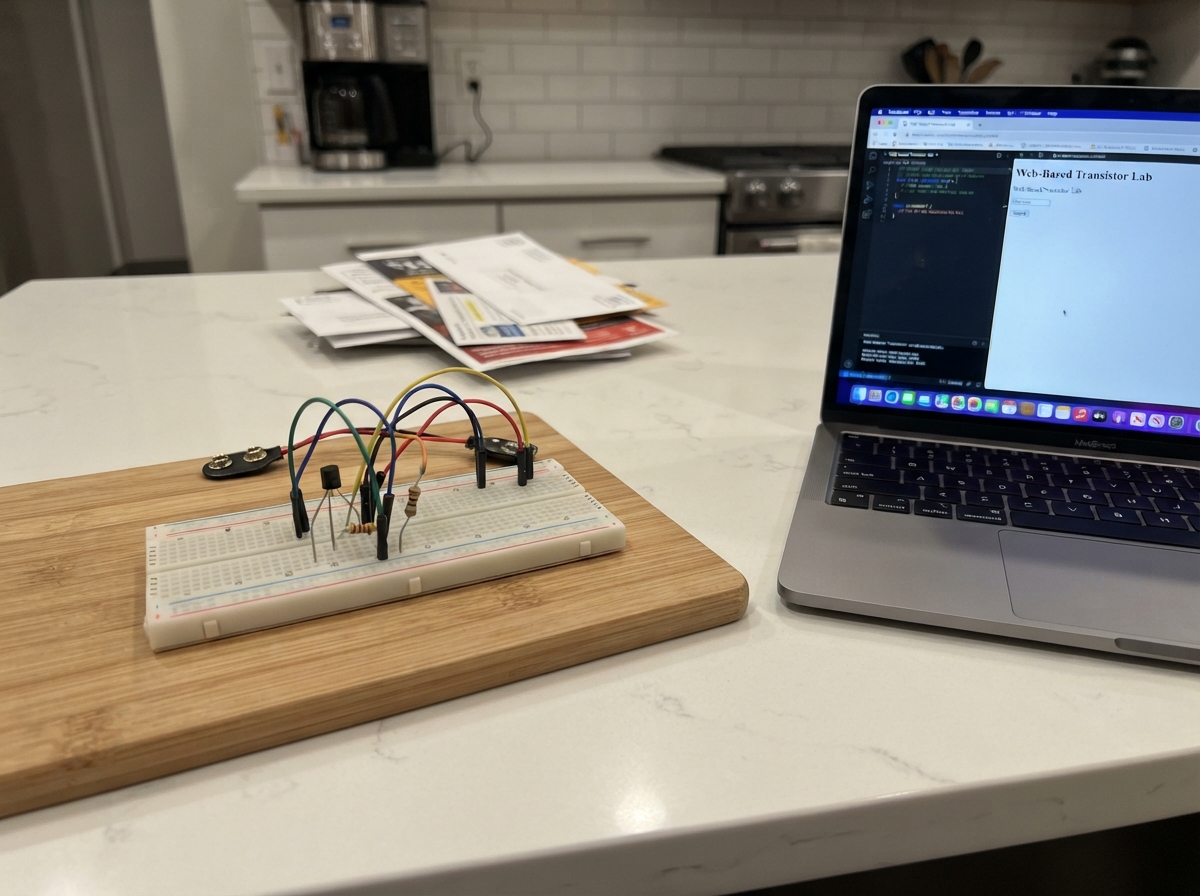
This project turns an ESP32 into an interactive transistor characterization tool. By connecting a 2N3904 NPN transistor with two resistors, the board measures how collector current varies with collector-emitter voltage—fundamental data for understanding transistor behavior. The guide includes a wiring diagram, parts list, and step-by-step assembly instructions to get the circuit working in minutes.
Once assembled and powered, the ESP32 hosts a web interface accessible from any browser on the local network. Users run automated sweeps that plot the transistor's output characteristics in real time, seeing live voltage and current measurements displayed on an interactive graph. This hands-on lab replaces expensive benchtop equipment and teaches transistor physics through direct experimentation.
Wiring diagram

Gather all the parts
Assemble it in 5 steps
1. Place the transistor
Put the 2N3904 transistor (npn_1) across the breadboard’s center gap with its flat face toward you. For the usual 2N3904 TO-92 package, the left, middle, and right legs are emitter, base, and collector; check the printing or supplier diagram because some look-alike transistors arrange their legs differently.
- Keep each transistor leg in a separate breadboard row so they cannot touch.
- Putting the collector and emitter in the wrong rows will give incorrect curves and may make the transistor appear not to work.
2. Connect the ground leg
Run one black jumper from the ESP32 GND pin to the breadboard ground row. Connect the transistor emitter leg to that same ground row.
- Every wire in this test shares this ground reference, so this connection must be firm.
- Do not connect the emitter to the ESP32 3V3 pin — that can damage the transistor or board.
3. Wire the base drive
Place the 10 kΩ resistor (base_resistor_10k) between ESP32 GPIO25 and the transistor base leg: one resistor leg goes to GPIO25 and its other leg goes to the base row. This resistor makes the small control current safe. GPIO25 → 10 kΩ resistor → transistor base (control signal).
- The resistor has no direction, so either leg can face GPIO25.
- Do not connect GPIO25 straight to the transistor base; the resistor is what limits the current.
4. Wire the collector test path
Place the 2.2 kΩ resistor (collector_resistor_220) between ESP32 GPIO26 and the transistor collector row. Add a second jumper from that collector row to ESP32 GPIO34. GPIO26 → 2.2 kΩ resistor → collector (test current); collector → GPIO34 (voltage measurement).
- GPIO34 only listens to the voltage at the collector row; it does not power the circuit.
- Make sure GPIO34 connects to the collector-side resistor leg, not the GPIO26-side leg, or the graph will not measure the transistor correctly.
5. Power the board and open the lab page
Inspect the four signal connections once more, then plug the ESP32 into USB. On your phone or computer, join the Wi-Fi network named Transistor-Lab using password measure123. Open a browser and visit http://192.168.4.1, then press Run characteristic sweep.
- The graph shows one colored collector-current curve for each base-drive level; no separate web server or internet connection is needed.
- Do not move breadboard wires while a sweep is running, because a loose wire can create misleading measurements.
Review all connections
1. Connections between "base_resistor_10k" and "ESP32"
2. Connections between "npn_1" and "ESP32"
3. Connections between "collector_resistor_220" and "ESP32"
Deploy the firmware
#include <Arduino.h>
#include <WiFi.h>
#include <WebServer.h>


// Forward declarations
function draw(data);
async function runTest();
float readCollectorVoltage();
void writeDacVoltage(int pin, float voltage);
void handleRun();

constexpr int BASE_DAC_PIN = 25;
constexpr int COLLECTOR_DAC_PIN = 26;
constexpr int COLLECTOR_SENSE_PIN = 34;
constexpr float DAC_MAX_V = 3.30f;
constexpr float BASE_RESISTOR_OHMS = 10000.0f;
constexpr float COLLECTOR_RESISTOR_OHMS = 2200.0f;
constexpr char AP_SSID[] = "Transistor-Lab";
constexpr char AP_PASSWORD[] = "measure123";

WebServer server(80);

const char PAGE[] PROGMEM = R"HTML(
<!doctype html><html><head><meta name="viewport" content="width=device-width,initial-scale=1">
<title>Transistor Virtual Lab</title><style>
body{font-family:system-ui,sans-serif;background:#101624;color:#edf3ff;margin:0;padding:18px;max-width:900px;margin:auto}h1{margin-bottom:4px}.card{background:#1b263b;padding:16px;border-radius:12px;margin:14px 0}button{background:#48b7ff;color:#04111f;border:0;border-radius:8px;padding:12px 16px;font-size:16px;font-weight:bold}canvas{background:#fff;border-radius:8px;width:100%;height:auto}.small{color:#b8c7df}.ok{color:#72e5a1}</style>
</head><body><h1>Transistor Virtual Lab</h1><p class="small">NPN output-characteristic measurement: collector current (I<sub>C</sub>) versus collector-emitter voltage (V<sub>CE</sub>).</p>
<div class="card"><button onclick="runTest()">Run characteristic sweep</button> <span id="status" class="small">Ready</span><p class="small">The board creates a small, safe test voltage and records the result. Do not change wires while a sweep is running.</p></div>
<div class="card"><canvas id="plot" width="820" height="480"></canvas><p id="summary" class="small">Press Run characteristic sweep to collect curves.</p></div>
<script>
function draw(data){const c=document.getElementById('plot'),x=c.getContext('2d'),W=c.width,H=c.height,L=65,R=22,T=25,B=58;
x.fillStyle='#fff';x.fillRect(0,0,W,H);x.strokeStyle='#d4dce9';x.lineWidth=1;
for(let i=0;i<=5;i++){let yy=T+i*(H-T-B)/5;x.beginPath();x.moveTo(L,yy);x.lineTo(W-R,yy);x.stroke();let xx=L+i*(W-L-R)/5;x.beginPath();x.moveTo(xx,T);x.lineTo(xx,H-B);x.stroke();}
x.strokeStyle='#15233a';x.lineWidth=2;x.beginPath();x.moveTo(L,T);x.lineTo(L,H-B);x.lineTo(W-R,H-B);x.stroke();x.fillStyle='#15233a';x.font='15px system-ui';x.fillText('Collector current, I_C (mA)',L,18);x.fillText('Collector-emitter voltage, V_CE (V)',W-255,H-16);
let maxI=Math.max(1,...data.flatMap(s=>s.points.map(p=>p.ic)));let colors=['#e83e8c','#2f80ed','#27ae60','#f2994a','#9b51e0','#d33636'];
data.forEach((s,k)=>{x.strokeStyle=colors[k%colors.length];x.lineWidth=2.5;x.beginPath();s.points.forEach((p,i)=>{let px=L+(p.vce/3.3)*(W-L-R),py=H-B-(p.ic/maxI)*(H-T-B);if(i)x.lineTo(px,py);else x.moveTo(px,py);});x.stroke();x.fillStyle=colors[k%colors.length];x.fillText('I_B '+s.ib.toFixed(3)+' mA',W-160,T+18*k);});
x.fillStyle='#15233a';for(let i=0;i<=5;i++){x.fillText((maxI*i/5).toFixed(1),8,H-B-i*(H-T-B)/5+5);x.fillText((3.3*i/5).toFixed(1),L+i*(W-L-R)/5-8,H-B+22);}}
async function runTest(){let b=document.querySelector('button');b.disabled=true;document.getElementById('status').textContent='Measuring…';try{let r=await fetch('/run');let d=await r.json();draw(d.curves);document.getElementById('summary').textContent='Collected '+d.curves.length+' base-drive curves, '+d.points+' readings total. Highest measured collector current: '+d.maxCurrent.toFixed(2)+' mA.';document.getElementById('status').textContent='Sweep complete';document.getElementById('status').className='ok';}catch(e){document.getElementById('status').textContent='Could not read the instrument.';}b.disabled=false;}
</script></body></html>
)HTML";

float readCollectorVoltage() {
  uint32_t total = 0;
  for (int i = 0; i < 8; ++i) {
    total += analogRead(COLLECTOR_SENSE_PIN);
    delay(2);
  }
  return (total / 8.0f) * DAC_MAX_V / 4095.0f;
}

void writeDacVoltage(int pin, float voltage) {
  voltage = constrain(voltage, 0.0f, DAC_MAX_V);
  dacWrite(pin, (uint8_t)lroundf(voltage * 255.0f / DAC_MAX_V));
}

void handleRun() {
  const float baseVoltages[] = {0.78f, 0.88f, 0.98f, 1.10f, 1.25f};
  String json = "{\"curves\":[";
  float maxCurrent = 0.0f;
  int readings = 0;
  for (size_t b = 0; b < sizeof(baseVoltages) / sizeof(baseVoltages[0]); ++b) {
    float baseV = baseVoltages[b];
    float estimatedIb = max(0.0f, (baseV - 0.70f) / BASE_RESISTOR_OHMS) * 1000.0f;
    writeDacVoltage(BASE_DAC_PIN, baseV);
    delay(35);
    if (b) json += ',';
    json += "{\"ib\":" + String(estimatedIb, 4) + ",\"points\":[";
    for (int step = 0; step <= 16; ++step) {
      float sourceV = 0.15f + step * (3.15f / 16.0f);
      writeDacVoltage(COLLECTOR_DAC_PIN, sourceV);
      delay(20);
      float vce = readCollectorVoltage();
      float ic = max(0.0f, (sourceV - vce) / COLLECTOR_RESISTOR_OHMS * 1000.0f);
      maxCurrent = max(maxCurrent, ic);
      if (step) json += ',';
      json += "{\"vce\":" + String(vce, 4) + ",\"ic\":" + String(ic, 4) + "}";
      readings++;
    }
    json += "]}";
  }
  writeDacVoltage(BASE_DAC_PIN, 0.0f);
  writeDacVoltage(COLLECTOR_DAC_PIN, 0.0f);
  json += "],\"points\":" + String(readings) + ",\"maxCurrent\":" + String(maxCurrent, 3) + "}";
  server.send(200, "application/json", json);
}

void setup() {
  analogReadResolution(12);
  analogSetPinAttenuation(COLLECTOR_SENSE_PIN, ADC_11db);
  dacWrite(BASE_DAC_PIN, 0);
  dacWrite(COLLECTOR_DAC_PIN, 0);
  WiFi.mode(WIFI_AP);
  WiFi.softAP(AP_SSID, AP_PASSWORD);
  server.on("/", HTTP_GET, [](){ server.send_P(200, "text/html", PAGE); });
  server.on("/run", HTTP_GET, handleRun);
  server.begin();
}

void loop() {
  server.handleClient();
}
Remix this project
Make it yours in one click
Open a full copy of this project in your own Schematik workspace — diagram, code, parts, and assembly steps included. Swap the sensor, add features, or redesign the whole thing with AI. The author's original stays untouched.