Community project
WiFi DeskBuddy Monitor
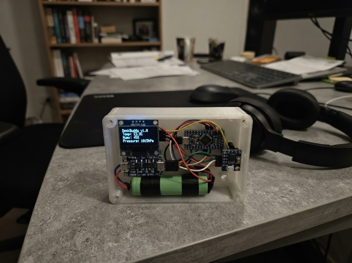
WiFi DeskBuddy Monitor is a compact, battery-powered desktop display that shows real-time temperature, barometric pressure, and altitude readings. Built around an ESP32 microcontroller, the device combines an SSD1306 OLED screen with a BMP180 environmental sensor, all powered by a protected 18650 Li-ion cell and boost converter for reliable operation.
This guide provides a complete parts list, wiring diagram, and step-by-step assembly instructions for building the DeskBuddy in its custom 3D-printed enclosure. Readers will also receive the full firmware with animated display rendering, sensor polling, and I²C communication code ready to upload to the ESP32.
Wiring diagram

Gather all the parts
Assemble it in 5 steps
1. Print the two-piece DeskBuddy enclosure
Print a base and removable front/lid in PETG or PLA. Start at 115 × 70 × 32 mm with 2.0–2.4 mm walls, then verify all openings against your actual modules. Provide M2/M2.5 mounting posts for the ESP32 and OLED, a separate restrained bay or commercial holder for the 18650 cell, a 28 × 14 mm OLED window, a TP4056 USB cutout, and a small vent pattern close to the BMP180.
- Make the OLED opening 0.5–1 mm larger than its visible glass area only after measuring your module.
- Use four M3 lid screws or a serviceable friction-fit lid so the battery remains inspectable.
- Do not make a tight crush-fit compartment around a bare Li-ion cell.
- Keep the TP4056 USB charging opening accessible with the enclosure closed.
2. Lay out the enclosure internals
Dry-fit the OLED behind the front window and the ESP32 behind it. Place the BMP180 near a small vented opening but away from direct airflow, the boost converter, and the ESP32 voltage regulator. Place the TP4056 USB connector at its external cutout. Keep the protected 18650 in its own bay along the long enclosure side and keep the ESP32 antenna end free of battery and metal obstructions.
- Use nylon standoffs, small screws, or thin foam tape so PCB solder joints cannot touch the battery.
- Provide internal wire channels or tie points so the lid cannot pinch a wire.
- The BMP180 measures pressure and temperature, not humidity.
- Avoid placing the BMP180 in a sealed heated pocket; this biases its temperature reading.
3. Build and test the protected battery supply
With the battery disconnected, wire battery_1 +V to charger_1 B+ and battery_1 GND to charger_1 B-. Wire charger_1 OUT+ to boost_1 VIN+ and charger_1 OUT- to boost_1 VIN-. USB charging connects only to the TP4056 input. Measure and adjust the boost converter to exactly 5.0 V at VOUT+/VOUT− before connecting it to the ESP32 VIN/5V and GND.
- Use short insulated wires and strain relief for battery and charger leads.
- Choose a TP4056 board with separate B+/B− battery terminals and OUT+/OUT− protected-load terminals.
- Reverse polarity or an incorrect boost voltage can damage equipment or heat the battery.
- Never connect the 5 V boost output to the ESP32 3V3 pin.
4. Install the shared I²C sensor and display wiring
Connect boost_1 VOUT+ to ESP32 VIN/5V and boost_1 VOUT− to ESP32 GND. Connect both oled_1 and bmp180_1 VCC to ESP32 3V3, and both grounds to ESP32 GND. Connect OLED SDA and BMP180 SDA together to GPIO21; connect OLED SCL and BMP180 SCL together to GPIO22. Mount the BMP180 board behind its vented opening without covering its pressure port or metal sensor package.
- The BMP180 and OLED intentionally share the same two I²C wires because their normal addresses differ: BMP180 0x77 and OLED 0x3C.
- Keep I²C leads short and route them away from the boost converter inductor.
- Use the BMP180 module's 3.3 V supply configuration so its I²C pull-ups never drive the ESP32 pins to 5 V.
- Do not seal the BMP180 pressure port with glue, foam, tape, or conformal coating.
5. Close the enclosure and perform the final check
Secure modules and wire bundles so no bare conductor or board underside can touch the battery. Insert the protected 18650 cell last, close the enclosure, and confirm the OLED window is clear, the BMP180 vent is clear, and the TP4056 USB port remains reachable. Use Schematik’s Deploy button to flash the prepared firmware.
- Altitude is calculated using standard sea-level pressure; it is useful as a relative trend unless you calibrate it for your local weather pressure.
- Expected runtime remains roughly 10 hours, depending on Wi-Fi use, display activity, battery condition, and boost efficiency.
- Charge Li-ion cells on a nonflammable surface and do not leave charging unattended.
- Disconnect the battery before opening the enclosure or changing wiring.
Review all connections
1. Connections between "oled_1" and "ESP32"
2. Connections between "battery_1" and "ESP32"
3. Connections between "charger_1" and "ESP32"
4. Connections between "boost_1" and "ESP32"
5. Connections between "bmp180_1" and "ESP32"
Deploy the firmware
#include <Arduino.h>
#include <Wire.h>
#include <Adafruit_GFX.h>
#include <Adafruit_SSD1306.h>
#include <Adafruit_BMP085.h>

void drawFace(int16_t centerX, int16_t centerY, uint8_t frame);
void drawScreen();
void readSensor();

constexpr uint8_t OLED_SDA_PIN = 21;
constexpr uint8_t OLED_SCL_PIN = 22;
constexpr uint8_t SCREEN_WIDTH = 128;
constexpr uint8_t SCREEN_HEIGHT = 64;
constexpr unsigned long SENSOR_INTERVAL_MS = 2000;
constexpr unsigned long ANIMATION_INTERVAL_MS = 50;
constexpr float SEA_LEVEL_PRESSURE_PA = 101325.0f;

Adafruit_SSD1306 display(SCREEN_WIDTH, SCREEN_HEIGHT, &Wire, -1);
Adafruit_BMP085 bmp;

float temperatureC = NAN;
float pressureHpa = NAN;
float altitudeM = NAN;
float previousTemperatureC = NAN;
float previousPressureHpa = NAN;
uint8_t animationFrame = 0;
unsigned long lastSensorRead = 0;
unsigned long lastAnimation = 0;
bool displayReady = false;
bool bmpReady = false;

void drawFace(int16_t centerX, int16_t centerY, uint8_t frame) {
  const int8_t bob = (frame % 20 < 10) ? 0 : 1;
  display.drawCircle(centerX, centerY + bob, 10, SSD1306_WHITE);
  display.fillCircle(centerX - 3, centerY - 2 + bob, 1, SSD1306_WHITE);
  display.fillCircle(centerX + 3, centerY - 2 + bob, 1, SSD1306_WHITE);
  display.drawLine(centerX - 4, centerY + 4 + bob, centerX + 4, centerY + 4 + bob, SSD1306_WHITE);
}

void drawScreen() {
  if (!displayReady) return;

  display.clearDisplay();
  display.setTextColor(SSD1306_WHITE);
  display.setTextSize(1);
  display.setCursor(0, 0);
  display.print("DeskBuddy BMP180");
  display.drawFastHLine(0, 10, SCREEN_WIDTH, SSD1306_WHITE);
  drawFace(116, 21, animationFrame);

  display.setTextSize(2);
  display.setCursor(0, 15);
  if (isnan(temperatureC)) {
    display.print("--.-C");
  } else {
    display.print(temperatureC, 1);
    display.print("C");
  }

  display.setTextSize(1);
  display.setCursor(0, 38);
  if (isnan(pressureHpa)) {
    display.print("Pressure: ----.- hPa");
  } else {
    display.print("Pressure: ");
    display.print(pressureHpa, 1);
    display.print(" hPa");
  }

  display.setCursor(0, 54);
  if (!bmpReady) {
    display.print("BMP180 not found");
  } else if (isnan(altitudeM)) {
    display.print("Reading sensor...");
  } else {
    display.print("Altitude: ");
    display.print(altitudeM, 0);
    display.print(" m");
  }
  display.display();
}

void readSensor() {
  if (!bmpReady) {
    bmpReady = bmp.begin();
    return;
  }

  const float nextTemperature = bmp.readTemperature();
  const float nextPressureHpa = bmp.readPressure() / 100.0f;
  if (!isnan(nextTemperature) && nextPressureHpa > 0.0f) {
    temperatureC = nextTemperature;
    pressureHpa = nextPressureHpa;
    altitudeM = bmp.readAltitude(SEA_LEVEL_PRESSURE_PA);
  }
}

void setup() {
  Wire.begin(OLED_SDA_PIN, OLED_SCL_PIN);
  displayReady = display.begin(SSD1306_SWITCHCAPVCC, 0x3C);
  bmpReady = bmp.begin();
  if (displayReady) {
    drawScreen();
  }
}

void loop() {
  const unsigned long now = millis();

  if (now - lastSensorRead >= SENSOR_INTERVAL_MS) {
    lastSensorRead = now;
    previousTemperatureC = temperatureC;
    previousPressureHpa = pressureHpa;
    readSensor();
    if (temperatureC != previousTemperatureC || pressureHpa != previousPressureHpa) {
      drawScreen();
    }
  }

  if (now - lastAnimation >= ANIMATION_INTERVAL_MS) {
    lastAnimation = now;
    animationFrame++;
    drawScreen();
  }
}
Remix this project
Make it yours in one click
Open a full copy of this project in your own Schematik workspace — diagram, code, parts, and assembly steps included. Swap the sensor, add features, or redesign the whole thing with AI. The author's original stays untouched.