Community project
WiFi-Synced Alarm Robot
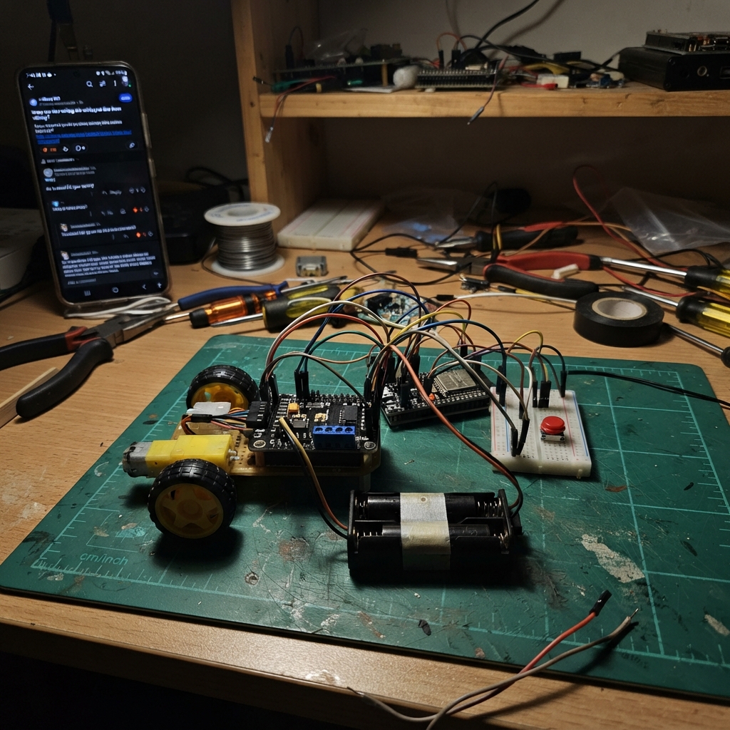
Build a WiFi-connected alarm robot that wakes you up by rolling around your room at a set time each day. The robot uses an ESP32 microcontroller to sync with an NTP time server, then automatically activates dual DC motors at your chosen alarm hour. A physical push button lets you stop the robot instantly when you're ready to get up.
This guide provides a complete wiring diagram, parts list, and step-by-step assembly instructions. You'll learn how to wire the L298N motor driver to control two independent motors, connect the battery pack with proper grounding, integrate the stop button for manual override, and upload the provided Arduino firmware. Safe testing procedures ensure everything works before deployment.
Wiring diagram

Gather all the parts
Assemble it in 6 steps
1. Mount the parts before wiring
Secure the ESP32-S3 PowerFeather, L298N driver, battery holder, button, and both gear motors to the robot chassis. Leave the AA holder switch off while you connect wires.
- Keep the motor wires away from the PowerFeather antenna end so it has a clearer Wi-Fi signal.
- Do not let bare motor or battery wires touch each other — the battery can get hot and damage parts if its wires are shorted.
2. Connect the two motors to the driver
Connect the left motor’s two wires to OUT1 and OUT2 on the L298N. Connect the right motor’s two wires to OUT3 and OUT4. If a wheel later turns the wrong way, switch only that motor’s two wires.
- Use a different wire color for each motor terminal so swapping a motor direction is easy.
- Keep each motor connected only to its matching pair of OUT terminals; do not connect either motor wire straight to the PowerFeather.
3. Wire the motor battery and shared ground
Connect the AA holder red wire to L298N VS (motor power), and its black wire to L298N GND. Connect L298N GND to a PowerFeather GND pin as well. Keep the L298N 5V logic connection as shown in the wiring diagram; do not feed the 6V AA pack into the PowerFeather 5V or 3V3 pin.
- The shared GND wire is essential: it lets the driver correctly understand the PowerFeather control signals.
- Do not swap the battery red and black wires — reversed power can damage the motor driver. Do not power the PowerFeather from the 6V AA holder.
4. Connect the four motor-control wires
Run wires from L298N IN1 to PowerFeather GPIO16, IN2 to GPIO17, IN3 to GPIO18, and IN4 to GPIO19. Leave the L298N ENA and ENB jumpers fitted so both motor channels are enabled.
- GPIO16 → IN1 (left motor direction), GPIO17 → IN2 (left motor direction), GPIO18 → IN3 (right motor direction), GPIO19 → IN4 (right motor direction).
- Do not move the motor wires to GPIO19 or GPIO20 — those pins are used by the PowerFeather USB connection.
5. Wire the stop button
Connect one button leg to PowerFeather GPIO21 and the other button leg to PowerFeather GND. The program holds GPIO21 high internally, so pressing the button connects it to ground and stops the alarm.
- On a four-leg button, use two legs from opposite sides; the two legs on the same side are already connected inside the button.
- Make sure the button wire goes to GPIO21, not 3V3 — connecting it to 3V3 would prevent the button from working as intended.
6. Power and test safely
With the AA holder still off, plug the PowerFeather into USB. Enter your Wi-Fi name and password in the sketch, then use Deploy. After it is deployed, turn on the AA battery holder and test at a clear time and open floor area.
- For a quick test, temporarily set TARGET_HOUR and TARGET_MINUTE to one or two minutes ahead, then press the button to silence it.
- Lift the robot so its wheels are clear of the table for the first motor test — it may move unexpectedly when the alarm starts.
Review all connections
1. Connections between "motor_battery" and "ESP32"
2. Connections between "motor_driver" and "ESP32"
3. Connections between "left_motor" and "ESP32"
4. Connections between "right_motor" and "ESP32"
5. Connections between "stop_button" and "ESP32"
Deploy the firmware
#include <Arduino.h>
#include <WiFi.h>
#include <time.h>

// Enter your own Wi-Fi details before deploying.

// Forward declarations
void stopRobot();
void moveForward();
void spinRight();
bool stopButtonPressed();
void startWiFiIfNeeded();
void updateMotion();

const char *WIFI_SSID = "YOUR_WIFI_SSID";
const char *WIFI_PASSWORD = "YOUR_WIFI_PASSWORD";

// Set this to your UTC offset in seconds. Example: India (IST) is 19800.
const long GMT_OFFSET_SECONDS = 19800;
const int DAYLIGHT_OFFSET_SECONDS = 0;
const char *NTP_SERVER = "pool.ntp.org";

const int MOTOR_A_IN1 = 16;
const int MOTOR_A_IN2 = 17;
const int MOTOR_B_IN3 = 18;
const int MOTOR_B_IN4 = 19;
const int STOP_BUTTON_PIN = 21;

const int TARGET_HOUR = 7;
const int TARGET_MINUTE = 0;
const unsigned long FORWARD_MS = 800;
const unsigned long TURN_MS = 400;
const unsigned long WIFI_RETRY_MS = 10000;
const unsigned long BUTTON_DEBOUNCE_MS = 35;

bool alarmActive = false;
int silencedYearDay = -1;
bool movingForward = true;
unsigned long motionStartedAt = 0;
bool lastButtonReading = HIGH;
bool stableButtonState = HIGH;
unsigned long lastButtonChangeAt = 0;
unsigned long lastWiFiAttemptAt = 0;

void stopRobot() {
  digitalWrite(MOTOR_A_IN1, LOW);
  digitalWrite(MOTOR_A_IN2, LOW);
  digitalWrite(MOTOR_B_IN3, LOW);
  digitalWrite(MOTOR_B_IN4, LOW);
}

void moveForward() {
  digitalWrite(MOTOR_A_IN1, HIGH);
  digitalWrite(MOTOR_A_IN2, LOW);
  digitalWrite(MOTOR_B_IN3, HIGH);
  digitalWrite(MOTOR_B_IN4, LOW);
}

void spinRight() {
  digitalWrite(MOTOR_A_IN1, HIGH);
  digitalWrite(MOTOR_A_IN2, LOW);
  digitalWrite(MOTOR_B_IN3, LOW);
  digitalWrite(MOTOR_B_IN4, HIGH);
}

bool stopButtonPressed() {
  const bool reading = digitalRead(STOP_BUTTON_PIN);
  const unsigned long now = millis();

  if (reading != lastButtonReading) {
    lastButtonChangeAt = now;
    lastButtonReading = reading;
  }

  if (now - lastButtonChangeAt >= BUTTON_DEBOUNCE_MS && reading != stableButtonState) {
    stableButtonState = reading;
    return stableButtonState == LOW;
  }
  return false;
}

void startWiFiIfNeeded() {
  if (WiFi.status() == WL_CONNECTED || (lastWiFiAttemptAt != 0 && millis() - lastWiFiAttemptAt < WIFI_RETRY_MS)) {
    return;
  }

  lastWiFiAttemptAt = millis();
  Serial.printf("Connecting to %s\n", WIFI_SSID);
  WiFi.begin(WIFI_SSID, WIFI_PASSWORD);
}

void updateMotion() {
  const unsigned long now = millis();
  const unsigned long phaseLength = movingForward ? FORWARD_MS : TURN_MS;

  if (now - motionStartedAt < phaseLength) {
    return;
  }

  movingForward = !movingForward;
  motionStartedAt = now;
  if (movingForward) {
    moveForward();
  } else {
    spinRight();
  }
}

void setup() {
  Serial.begin(115200);

  pinMode(MOTOR_A_IN1, OUTPUT);
  pinMode(MOTOR_A_IN2, OUTPUT);
  pinMode(MOTOR_B_IN3, OUTPUT);
  pinMode(MOTOR_B_IN4, OUTPUT);
  pinMode(STOP_BUTTON_PIN, INPUT_PULLUP);
  stopRobot();

  WiFi.mode(WIFI_STA);
  startWiFiIfNeeded();
  configTime(GMT_OFFSET_SECONDS, DAYLIGHT_OFFSET_SECONDS, NTP_SERVER);
}

void loop() {
  startWiFiIfNeeded();

  struct tm now;
  const bool timeValid = getLocalTime(&now, 10);
  if (!timeValid) {
    stopRobot();
    alarmActive = false;
    delay(10);
    return;
  }

  const bool scheduledMinute = now.tm_hour == TARGET_HOUR && now.tm_min == TARGET_MINUTE;
  const bool wasSilencedToday = silencedYearDay == now.tm_yday;

  if (scheduledMinute && !wasSilencedToday && !alarmActive) {
    alarmActive = true;
    movingForward = true;
    motionStartedAt = millis();
    moveForward();
    Serial.println("Alarm active: robot is moving.");
  }

  if (alarmActive) {
    if (stopButtonPressed()) {
      alarmActive = false;
      silencedYearDay = now.tm_yday;
      stopRobot();
      Serial.println("Alarm silenced until tomorrow.");
    } else {
      updateMotion();
    }
  } else {
    stopRobot();
  }

  delay(10);
}
Remix this project
Make it yours in one click
Open a full copy of this project in your own Schematik workspace — diagram, code, parts, and assembly steps included. Swap the sensor, add features, or redesign the whole thing with AI. The author's original stays untouched.