Community project
You Are Senior Robotics Hardware Engineer Produc
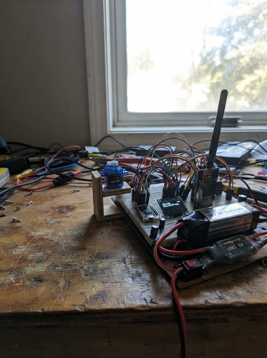
This guide builds a hexapod robot controlled by an ESP32 microcontroller with wireless command capability. The robot uses twelve SG90 servos (two per leg) to achieve coordinated walking motion, an MPU-6050 IMU for balance and roll sensing, an nRF24L01+ radio module for remote operation, and an SSD1306 OLED display for real-time telemetry feedback. Power comes from a 2S LiPo battery regulated through a Hobbywing UBEC with proper fusing and switching for safe operation.
This guide provides a complete wiring diagram, detailed parts list with specifications, the full ESP32 firmware with servo control and radio communication routines, and step-by-step assembly instructions. Learn how to configure the power distribution safely, calibrate servo endpoints, integrate the inertial measurement unit, set up wireless telemetry packets, and perform a methodical first-power safety check before autonomous operation.
Wiring diagram

Gather all the parts
Assemble it in 6 steps
1. Fit the fused battery input
With the battery unplugged, connect the 2S battery pack positive lead to the fuse-holder/switch IN+ terminal (battery protection). Connect the switch OUT+ terminal to UBEC VIN+ (regulated-power input). Connect battery negative directly to UBEC VIN- (power return). Install a 10 A fuse only after every wire has been checked with the multimeter.
- Use silicone-insulated 18 AWG wire, or thicker, for every battery, fuse, switch, and UBEC wire.
- The switch must be rated for at least 10 A DC; an ordinary small breadboard switch is not safe here.
- A reversed battery connection can destroy the UBEC and create a hot wire or fire risk. Check polarity with the meter before inserting the fuse.
- Do not use the battery balance plug to run the robot; it is for balance charging only.
2. Set the servo regulator before connecting servos
Keep the UBEC 5 V output disconnected from every servo. Turn on the fused switch and measure UBEC VOUT+ to VOUT- with the multimeter. Adjust it, if adjustable, until it reads 5.0 V. Turn the switch off again before making the servo connections.
- Put a label saying “5.0 V SERVO RAIL” on the UBEC output wires.
- Check the voltage again after 30 seconds with no load; it should remain close to 5.0 V.
- Do not connect the UBEC 5 V output to the ESP32 3V3 pin — 5 V on that pin can damage the ESP32.
- Never adjust or move wiring while the battery is connected.
3. Make the heavy servo power junction
Join UBEC VOUT+ to all twelve servo red wires (5 V power). Join UBEC VOUT- to all twelve servo brown or black wires (ground). Put the 2200 µF capacitor across that same junction: its marked positive lead goes to the red-wire 5 V junction, and its striped negative lead goes to the brown/black ground junction.
- Use a proper soldered distribution block, screw terminal block, or thick crimped harness; do not pass twelve servo power leads through thin breadboard tracks.
- Use 20–22 AWG wire for short branches to individual SG90 servos and 18 AWG or thicker for the main UBEC-to-junction wires.
- A reversed electrolytic capacitor can burst. The striped side is negative and must go to the ground junction.
- Do not let a loose servo power lead touch the chassis or another wire; the battery can supply enough current to melt a jumper wire.
4. Join the controller ground and servo signals
Connect the heavy servo ground junction to one ESP32 A GND pin (shared signal reference). Then connect each servo orange or yellow signal lead: L1 femur to GPIO1, L1 tibia to GPIO2, L2 femur to GPIO3, L2 tibia to GPIO13, L3 femur to GPIO14, L3 tibia to GPIO16, R1 femur to GPIO17, R1 tibia to GPIO25, R2 femur to GPIO26, R2 tibia to GPIO27, R3 femur to GPIO32, and R3 tibia to GPIO33 (position signals).
- Label every servo before installing it; this avoids having to trace twelve similar cables later.
- Servo wire colours are usually red for power, brown/black for ground, and orange/yellow for the signal.
- The servo ground and ESP32 GND must be joined or the position signals will be unreliable.
- GPIO1, GPIO2, GPIO3, GPIO5, GPIO12, and GPIO15 can change briefly at startup. Keep the robot raised so its legs cannot push against the bench during first power-up.
5. Wire the balance sensor, display, and radio
Connect MPU6050 VIN and OLED VCC to ESP32 3V3 (power); connect both grounds to ESP32 GND (ground); connect both SDA pins to GPIO21 (data) and both SCL pins to GPIO22 (clock). Connect the NRF24L01 VCC to 3V3 (power), GND to GND (ground), CE to GPIO4 (control), CSN to GPIO5 (select), SCK to GPIO18 (clock), MOSI to GPIO23 (data to radio), and MISO to GPIO19 (data from radio). Keep the radio wires short and place a 10–100 µF capacitor directly across its VCC and GND pins.
- Mount the MPU6050 flat and close to the centre of the chassis so its tilt readings represent the robot body.
- Keep the radio away from the UBEC and main servo power wires to reduce radio interference.
- The NRF24L01 is 3.3 V only; connecting its VCC to 5 V can permanently damage it.
- Make sure VCC and GND are not swapped on the OLED and MPU6050 — swapped power can damage the modules.
6. Perform the first powered safety check
Raise the chassis so all legs are free, then connect ESP32 A to USB and press Deploy in Schematik. The OLED should show CALIBRATION LOCK. With the battery switch still off, confirm the controller starts normally. Then turn on the fused servo rail for only a few seconds: every servo should hold its neutral position without twitching hard, heating, or pulling the chassis. Turn the switch off immediately if anything is wrong.
- Test the power system first with no leg load if possible, then add one leg pair at a time.
- The current firmware deliberately keeps movement locked; it is for wiring and neutral-angle calibration, not walking yet.
- Keep hands, hair, and loose wires clear of the legs. A servo can move suddenly during a wiring fault or ESP32 restart.
- If the UBEC voltage falls below about 4.8 V, any wire gets warm, or the ESP32 resets, switch off immediately and find the wiring fault before trying again.
Review all connections
1. Connections between "servo_l1_femur" and "ESP32"
2. Connections between "imu_1" and "ESP32"
3. Connections between "oled_legs" and "ESP32"
4. Connections between "radio_legs" and "ESP32"
5. Connections between "servo_l1_tibia" and "ESP32"
6. Connections between "servo_l2_femur" and "ESP32"
7. Connections between "servo_l2_tibia" and "ESP32"
8. Connections between "servo_l3_femur" and "ESP32"
9. Connections between "servo_l3_tibia" and "ESP32"
10. Connections between "servo_r1_femur" and "ESP32"
11. Connections between "servo_r1_tibia" and "ESP32"
12. Connections between "servo_r2_femur" and "ESP32"
13. Connections between "servo_r2_tibia" and "ESP32"
14. Connections between "servo_r3_femur" and "ESP32"
15. Connections between "servo_r3_tibia" and "ESP32"
16. Connections between "battery_2s" and "ESP32"
17. Connections between "master_fuse_switch" and "ESP32"
18. Connections between "ubec_5v_10a" and "ESP32"
19. Connections between "servo_bulk_cap" and "ESP32"
Deploy the firmware
#include <Arduino.h>
#include <Wire.h>
#include <SPI.h>
#include <ESP32Servo.h>
#include <RF24.h>
#include <Adafruit_GFX.h>
#include <Adafruit_SSD1306.h>


struct TelemetryPacket {
  uint8_t mode;
  uint16_t distanceCm;
  int16_t rollDeciDeg;
  uint8_t speed;
  uint8_t flags;
  uint8_t reserved[25];
};


// Forward declarations
void centerAllServos();
bool writeMpuRegister(uint8_t reg, uint8_t value);
void updateRoll();
void queueTelemetry(uint8_t pipe);
void processRadio();
void updateDisplay();

constexpr uint8_t L1_FEMUR_PIN = 1;
constexpr uint8_t L1_TIBIA_PIN = 2;
constexpr uint8_t L2_FEMUR_PIN = 3;
constexpr uint8_t L2_TIBIA_PIN = 13;
constexpr uint8_t L3_FEMUR_PIN = 14;
constexpr uint8_t L3_TIBIA_PIN = 16;
constexpr uint8_t R1_FEMUR_PIN = 17;
constexpr uint8_t R1_TIBIA_PIN = 25;
constexpr uint8_t R2_FEMUR_PIN = 26;
constexpr uint8_t R2_TIBIA_PIN = 27;
constexpr uint8_t R3_FEMUR_PIN = 32;
constexpr uint8_t R3_TIBIA_PIN = 33;

constexpr uint8_t NRF_CE_PIN = 4;
constexpr uint8_t NRF_CSN_PIN = 5;
constexpr uint8_t NRF_SCK_PIN = 18;
constexpr uint8_t NRF_MISO_PIN = 19;
constexpr uint8_t NRF_MOSI_PIN = 23;
constexpr uint8_t I2C_SDA_PIN = 21;
constexpr uint8_t I2C_SCL_PIN = 22;

constexpr uint8_t MPU6050_ADDRESS = 0x68;
constexpr uint8_t OLED_ADDRESS = 0x3C;
constexpr uint16_t SERVO_MIN_US = 1000;
constexpr uint16_t SERVO_CENTER_US = 1500;
constexpr uint16_t SERVO_MAX_US = 2000;
constexpr uint32_t DISPLAY_PERIOD_MS = 250;


static_assert(sizeof(TelemetryPacket) == 32, "Telemetry packet must be 32 bytes");

const uint8_t servoPins[12] = {
  L1_FEMUR_PIN, L1_TIBIA_PIN, L2_FEMUR_PIN, L2_TIBIA_PIN,
  L3_FEMUR_PIN, L3_TIBIA_PIN, R1_FEMUR_PIN, R1_TIBIA_PIN,
  R2_FEMUR_PIN, R2_TIBIA_PIN, R3_FEMUR_PIN, R3_TIBIA_PIN
};
const uint8_t radioAddress[6] = "HXPD1";

Servo servos[12];
RF24 radio(NRF_CE_PIN, NRF_CSN_PIN);
Adafruit_SSD1306 display(128, 64, &Wire, -1);

bool imuPresent = false;
bool oledPresent = false;
bool radioPresent = false;
bool safeStop = true;
uint8_t lastCommand = 0;
int16_t rollDeciDeg = 0;
uint32_t lastDisplayMs = 0;

void centerAllServos() {
  for (uint8_t i = 0; i < 12; ++i) {
    servos[i].writeMicroseconds(SERVO_CENTER_US);
  }
}

bool writeMpuRegister(uint8_t reg, uint8_t value) {
  Wire.beginTransmission(MPU6050_ADDRESS);
  Wire.write(reg);
  Wire.write(value);
  return Wire.endTransmission() == 0;
}

void updateRoll() {
  if (!imuPresent) return;
  Wire.beginTransmission(MPU6050_ADDRESS);
  Wire.write(0x3B);
  if (Wire.endTransmission(false) != 0 || Wire.requestFrom(MPU6050_ADDRESS, (uint8_t)6) != 6) {
    imuPresent = false;
    return;
  }
  const int16_t ax = (Wire.read() << 8) | Wire.read();
  const int16_t ay = (Wire.read() << 8) | Wire.read();
  const int16_t az = (Wire.read() << 8) | Wire.read();
  const float roll = atan2f((float)ay, sqrtf((float)ax * ax + (float)az * az)) * 57.29578f;
  rollDeciDeg = (int16_t)lroundf(roll * 10.0f);
}

void queueTelemetry(uint8_t pipe) {
  TelemetryPacket packet = {};
  packet.mode = 0;       // Motion remains locked until mechanical calibration is complete.
  packet.distanceCm = 0; // Node B is not connected in this controller build.
  packet.rollDeciDeg = rollDeciDeg;
  packet.speed = 0;
  packet.flags = (safeStop ? 0x01 : 0x00) | (imuPresent ? 0x08 : 0x00);
  radio.writeAckPayload(pipe, &packet, sizeof(packet));
}

void processRadio() {
  if (!radioPresent) return;
  uint8_t pipe = 0;
  while (radio.available(&pipe)) {
    uint8_t command[32] = {};
    radio.read(command, sizeof(command));
    lastCommand = command[0];

    // STOP and EMERGENCY always leave the robot centered and stopped.
    // Advance/turn/calibration remain locked until the chassis and neutral angles
    // are calibrated with the fused, dedicated 5 V UBEC servo rail.
    safeStop = true;
    centerAllServos();
    queueTelemetry(pipe);
  }
}

void updateDisplay() {
  if (!oledPresent || millis() - lastDisplayMs < DISPLAY_PERIOD_MS) return;
  lastDisplayMs = millis();
  display.clearDisplay();
  display.setTextColor(SSD1306_WHITE);
  display.setTextSize(1);
  display.setCursor(0, 0);
  display.println("HEXAPOD NODE A");
  display.setCursor(0, 14);
  display.println("CALIBRATION LOCK");
  display.setCursor(0, 28);
  display.print("RF: ");
  display.println(radioPresent ? "OK" : "ERR");
  display.setCursor(0, 40);
  display.print("IMU: ");
  display.println(imuPresent ? "OK" : "ERR");
  display.setCursor(0, 52);
  display.print("Roll ");
  display.print(rollDeciDeg / 10.0f, 1);
  display.print(" C ");
  display.print(lastCommand, HEX);
  display.display();
}

void setup() {
  Wire.begin(I2C_SDA_PIN, I2C_SCL_PIN);
  Wire.setClock(400000);

  Wire.beginTransmission(MPU6050_ADDRESS);
  imuPresent = Wire.endTransmission() == 0;
  if (imuPresent) imuPresent = writeMpuRegister(0x6B, 0x00);
  oledPresent = display.begin(SSD1306_SWITCHCAPVCC, OLED_ADDRESS);

  ESP32PWM::allocateTimer(0);
  ESP32PWM::allocateTimer(1);
  ESP32PWM::allocateTimer(2);
  ESP32PWM::allocateTimer(3);
  for (uint8_t i = 0; i < 12; ++i) {
    servos[i].setPeriodHertz(50);
    servos[i].attach(servoPins[i], SERVO_MIN_US, SERVO_MAX_US);
  }
  centerAllServos();

  SPI.begin(NRF_SCK_PIN, NRF_MISO_PIN, NRF_MOSI_PIN, NRF_CSN_PIN);
  radioPresent = radio.begin();
  if (radioPresent) {
    radio.setChannel(108);
    radio.setDataRate(RF24_250KBPS);
    radio.setPALevel(RF24_PA_LOW);
    radio.setPayloadSize(32);
    radio.enableAckPayload();
    radio.openReadingPipe(1, radioAddress);
    queueTelemetry(1);
    radio.startListening();
  }
}

void loop() {
  processRadio();
  updateRoll();
  centerAllServos();
  updateDisplay();
}
Remix this project
Make it yours in one click
Open a full copy of this project in your own Schematik workspace — diagram, code, parts, and assembly steps included. Swap the sensor, add features, or redesign the whole thing with AI. The author's original stays untouched.