On this page
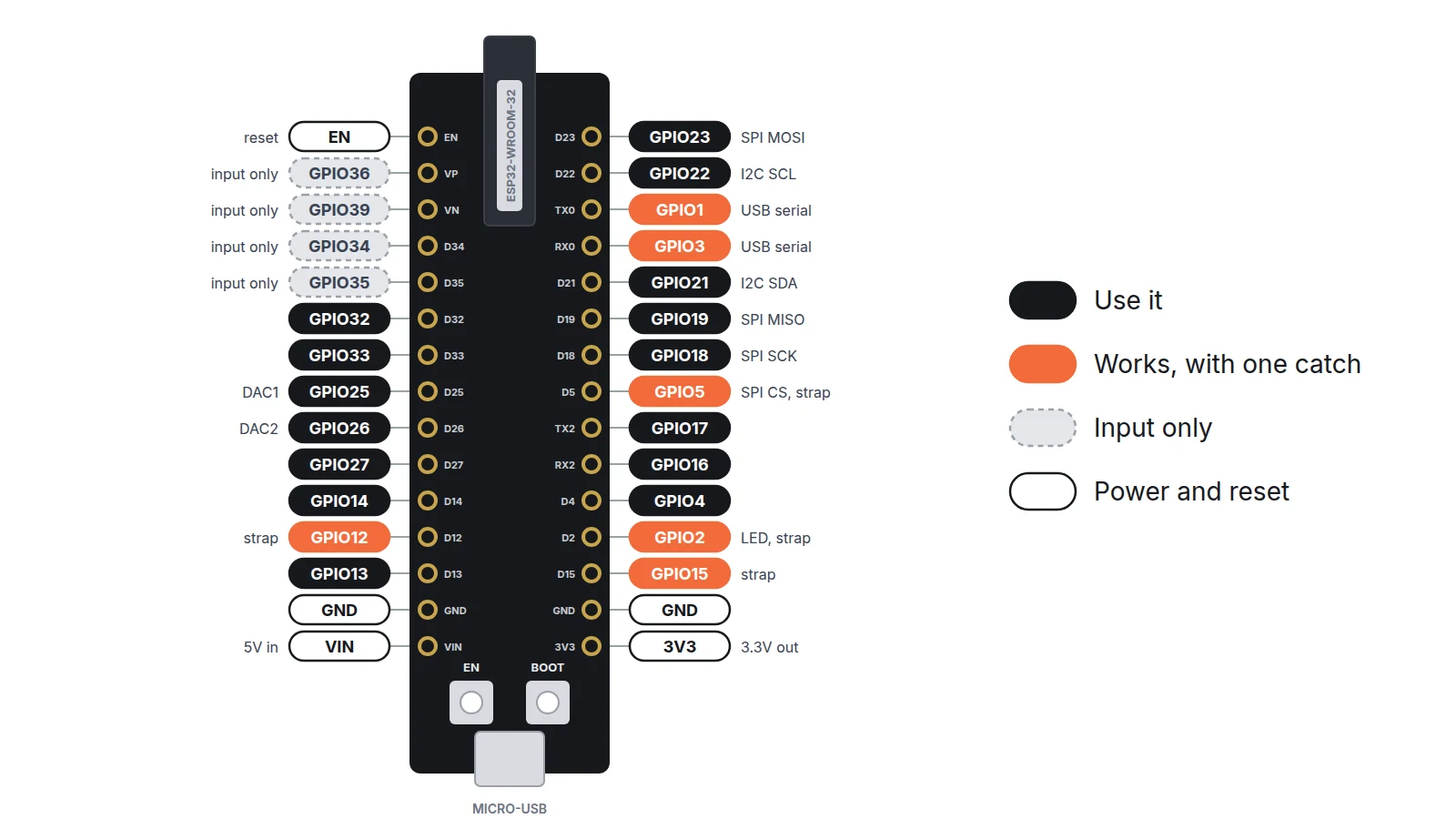
The 30-pin ESP32 DevKit V1 has two rows of 15 pins, and 25 of them are GPIO (general-purpose input/output) pins. Most are safe to wire to anything. A few have a catch at power-up or while Wi-Fi is on.
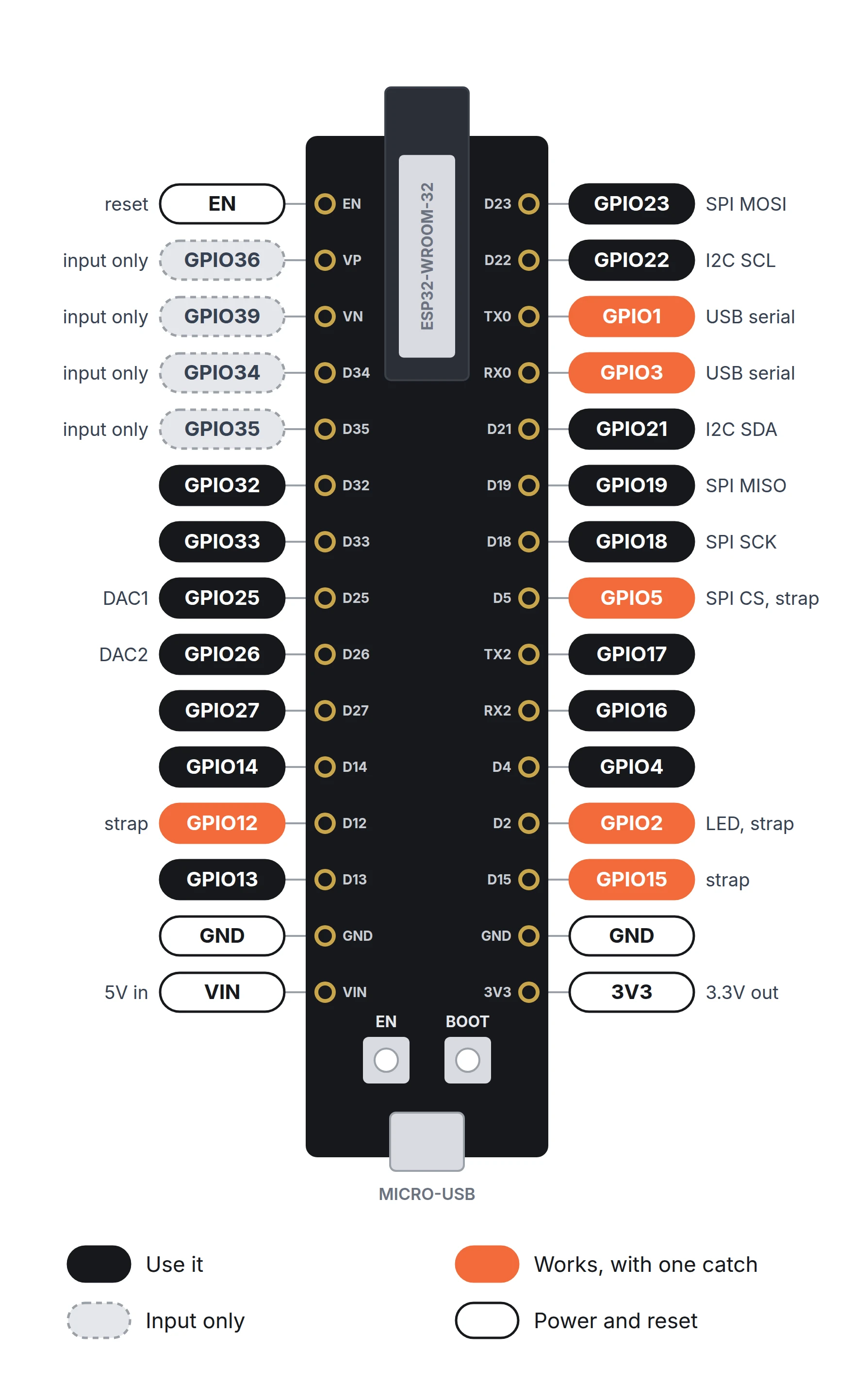
If you just need a pin for an LED, a button or a sensor, start with GPIO13, 14, 16, 17, 18, 19, 21, 22, 23, 25, 26, 27, 32 or 33.
Do not connect 5 V to a GPIO pin. Every input takes at most 3.3 V plus 0.3 V.
Every pin, side by side
Both tables run from the antenna end of the ESP32-WROOM-32 module down to the USB port. The silkscreen is the label printed on the board. The DevKit V1 part page has the same pins with their voltages.
Left row
| Silkscreen | GPIO | Notes |
|---|---|---|
| EN | - | Reset |
| VP | GPIO36 | Input only, ADC1 |
| VN | GPIO39 | Input only, ADC1 |
| D34 | GPIO34 | Input only, ADC1 |
| D35 | GPIO35 | Input only, ADC1 |
| D32 | GPIO32 | ADC1, touch |
| D33 | GPIO33 | ADC1, touch |
| D25 | GPIO25 | DAC1, ADC2 |
| D26 | GPIO26 | DAC2, ADC2 |
| D27 | GPIO27 | ADC2, touch |
| D14 | GPIO14 | ADC2, touch |
| D12 | GPIO12 | Strapping, ADC2, touch |
| D13 | GPIO13 | ADC2, touch |
| GND | - | Ground |
| VIN | - | 5 V in |
Right row
| Silkscreen | GPIO | Notes |
|---|---|---|
| D23 | GPIO23 | SPI MOSI |
| D22 | GPIO22 | I2C SCL |
| TX0 | GPIO1 | USB serial |
| RX0 | GPIO3 | USB serial |
| D21 | GPIO21 | I2C SDA |
| D19 | GPIO19 | SPI MISO |
| D18 | GPIO18 | SPI SCK |
| D5 | GPIO5 | SPI CS, strapping |
| TX2 | GPIO17 | Free |
| RX2 | GPIO16 | Free |
| D4 | GPIO4 | ADC2, touch |
| D2 | GPIO2 | Blue LED, strapping |
| D15 | GPIO15 | Strapping, ADC2, touch |
| GND | - | Ground |
| 3V3 | - | 3.3 V out |
Pins to avoid, and why
| Pins | Catch | What happens |
|---|---|---|
| GPIO34, 35, 36, 39 | Input only | No output, no pull-ups |
| GPIO1, 3 | USB serial | Uploads and Serial break |
| GPIO12 | Strapping | High at power-up: wrong flash voltage |
| GPIO2 | Strapping, LED | Low with BOOT held: flash mode |
| GPIO15 | Strapping | Low at boot: no boot log |
| ADC2 pins | Wi-Fi | No analog reads with Wi-Fi on |
Input-only pins. GPIO34, 35, 36 and 39 can read but not drive anything, and they have no internal pull-up or pull-down resistor. A button on one of them needs its own resistor to 3.3 V or GND.
Strapping pins. A strapping pin is one the chip reads at reset to decide how to boot. After boot it works like any other pin, so the only catch is what you connect to it at power-up.
- GPIO12 is pulled low inside the chip. If a part holds it high at power-up, the chip powers its flash memory at 1.8 V instead of 3.3 V. The WROOM-32 datasheet says to keep this pin low at power-up.
- GPIO2 is pulled low and drives the blue LED. GPIO0 and GPIO2 both low at reset puts the chip in download mode, the mode it uses to receive new code. GPIO0 is the BOOT button and is not on the headers.
- GPIO15 is pulled high. Held low at boot, it silences the boot messages on TX0.
- GPIO5 is pulled high and is also the Arduino SPI chip-select pin.
USB serial pins. GPIO1 (TX0) and GPIO3 (RX0) go to the CP2102 USB-to-serial chip. That is how your code gets uploaded and how Serial.print reaches your computer. Wire something else to them and both can fail.
Flash pins. GPIO6 to GPIO11 connect to the module's flash memory. The 30-pin board does not break them out, so there is nothing to avoid here.
ADC2 with Wi-Fi. The ESP32 has two analog-to-digital converters (ADCs, which turn a voltage into a number). ADC2 cannot be read while Wi-Fi is on. For a sensor in a Wi-Fi project, use an ADC1 pin: GPIO32, 33, 34, 35, 36 or 39.
Default pins in Arduino
| Function | Pins | Notes |
|---|---|---|
| I2C | SDA 21, SCL 22 | Wire uses these |
| SPI | MOSI 23, MISO 19, SCK 18, CS 5 | SPI uses these |
| UART0 | TX 1, RX 3 | USB upload and Serial |
| UART2 | TX2 17, RX2 16 | Pass them to Serial2.begin |
| LED | GPIO2 | LED_BUILTIN |
The board prints RX2 and TX2 next to GPIO16 and GPIO17, but version 3 of the Arduino-ESP32 core starts Serial2 on RX 4 and TX 25. Name the pins to use the labelled ones:
Serial2.begin(9600, SERIAL_8N1, 16, 17);
Analog, touch and DAC pins
| Type | GPIO | Notes |
|---|---|---|
| ADC1 | 32, 33, 34, 35, 36, 39 | Works with Wi-Fi on |
| ADC2 | 2, 4, 12, 13, 14, 15, 25, 26, 27 | Off while Wi-Fi is on |
| DAC | 25, 26 | Real voltage out |
| Touch | 2, 4, 12, 13, 14, 15, 27, 32, 33 | Senses a fingertip |
A DAC (digital-to-analog converter) sets a real voltage on the pin, not the fast on-off signal of PWM. Touch pins sense a fingertip on a bare wire or pad.
Power pins
| Pin | Role | Notes |
|---|---|---|
| VIN | Power in | 5 V, feeds the 3.3 V regulator |
| 3V3 | Power out | Regulator output |
| GND | Ground | One in each row |
Over USB, the board powers itself and VIN is not needed. The ESP32 power guide covers the ways to power an ESP32 board.
DevKit V1 vs the 38-pin DevKitC
Espressif's own ESP32-DevKitC has 38 pins and the same chip. Every GPIO on the DevKit V1 is on it too. The extra 8 are GPIO0, GPIO6 to GPIO11 (the flash pins, which Espressif says to avoid) and one more GND. Its 5 V pin is labelled 5V instead of VIN.
The ESP32-S3-DevKitC-1 is a different chip with different pin numbers. For that board, use the ESP32-S3-DevKitC-1 pinout.
Real builds on this board
These three guides from Schematik run on the DevKit V1. All of them put an SSD1306 OLED on the default I2C pins, GPIO21 and GPIO22.
ESP32 ultrasonic parking sensor. An HC-SR04P with TRIG on GPIO27 and ECHO on GPIO26, a passive buzzer on GPIO25, and green, yellow and red LEDs on GPIO14, 12 and 13. Green means far away. Red and faster beeps mean stop. The LED on GPIO12 is fine because an LED with a resistor to GND never pulls the pin high at boot.
You can run it without any parts in the simulator.
ESP32 desk presence busy light. A PIR motion sensor on GPIO27, a button on GPIO26 and a WS2812B LED ring driven from GPIO4 through a 74AHCT125 level shifter, which lifts the 3.3 V data signal to the 5 V the ring expects. The ring shows green for free, orange for recently active and red for busy.
RFID treasure chest. An MFRC522 reader on the default SPI pins (MOSI 23, MISO 19, SCK 18, CS 5) with RST on GPIO27, an SG90 servo latch on GPIO26 and a piezo on GPIO25. Tap the right tag and the servo swings the latch open.
New to breadboards? ESP32 on a breadboard shows where the board goes and how the rails work. More builds are in ESP32 projects.
Start a build
Open Schematik, name the DevKit V1 and describe what you want to make. It picks the pins and writes the code. Paste this to try it:
ESP32 DevKit V1 with a BME280 on I2C and a button on GPIO27 that shows the temperature on an SSD1306 OLED
Keep building from here
Jump into a step-by-step build, or open Schematik and turn your own idea into code, wiring, and assembly instructions.
Related posts
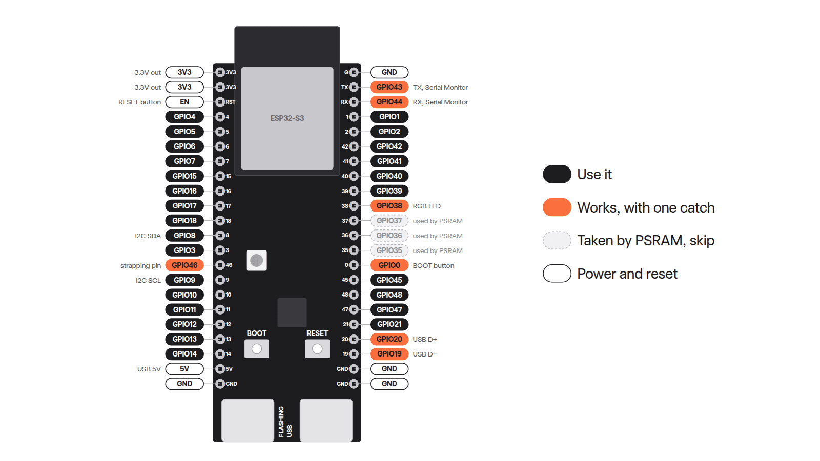
ESP32-S3-DevKitC-1 pinout: which pins to use first
Every pin on the ESP32-S3-DevKitC-1, sorted into pins you can use, pins with one catch and three pins to skip. Plus what the BOOT button does.
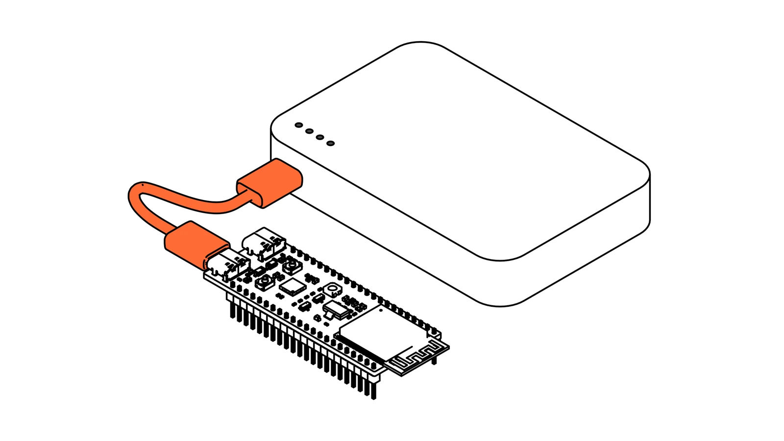
How to power an ESP32: USB, the 5V pin, the 3V3 pin and batteries
There are four ways to get power into an ESP32, and each one goes through the board differently. Here is the path each one takes, the numbers from the datasheets and how to make a battery last for months.
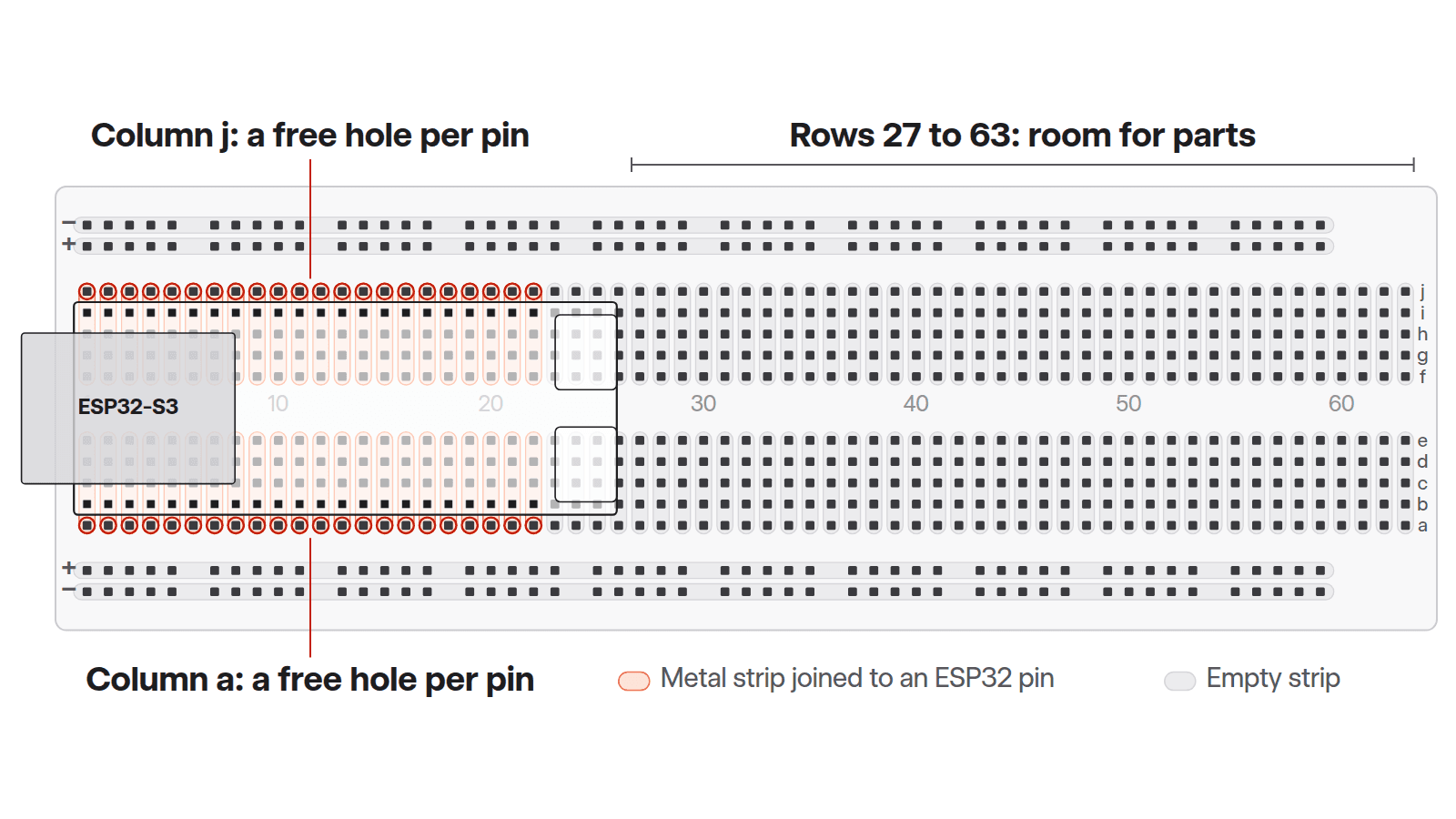
How to put an ESP32 on a breadboard and wire your first parts
Where the ESP32 goes on a breadboard, why it leaves you one free hole per pin and how to wire power, an LED and the first sensors of a room monitor.
Related builds
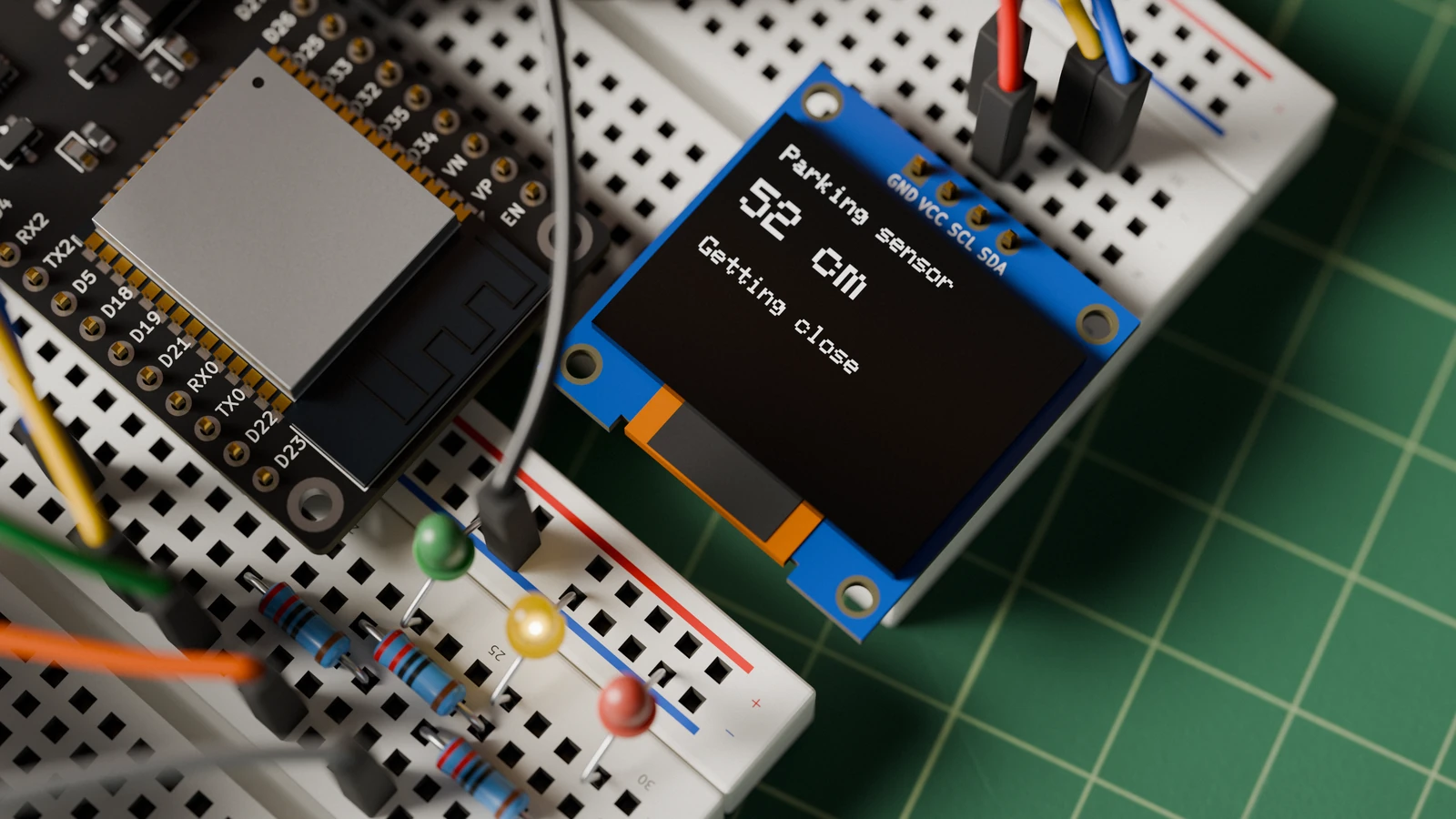
How to Build an ESP32 Ultrasonic Parking Sensor
Build a bench-safe ESP32 parking sensor with an HC-SR04P ultrasonic module, SSD1306 OLED, three warning LEDs, and a passive buzzer.
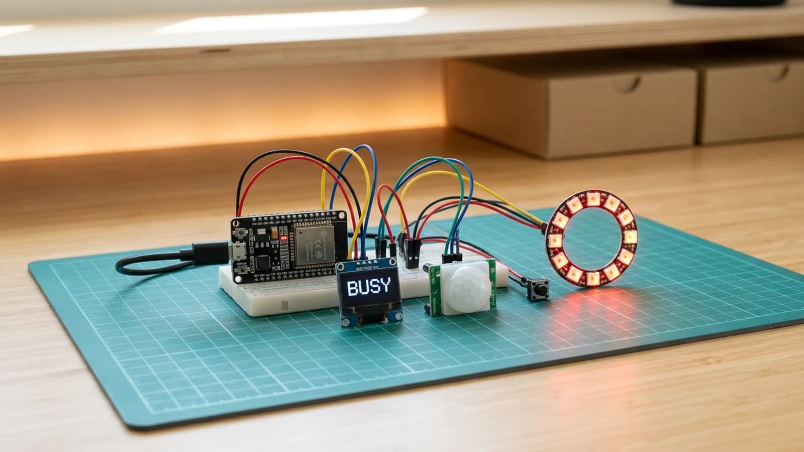
How to Build an ESP32 Desk Presence Busy Light
Build an ESP32 desk presence light that shows whether your workspace is free, recently active, or manually set to busy. Includes PIR wiring, OLED status text, LED ring feedback, and complete Arduino code.
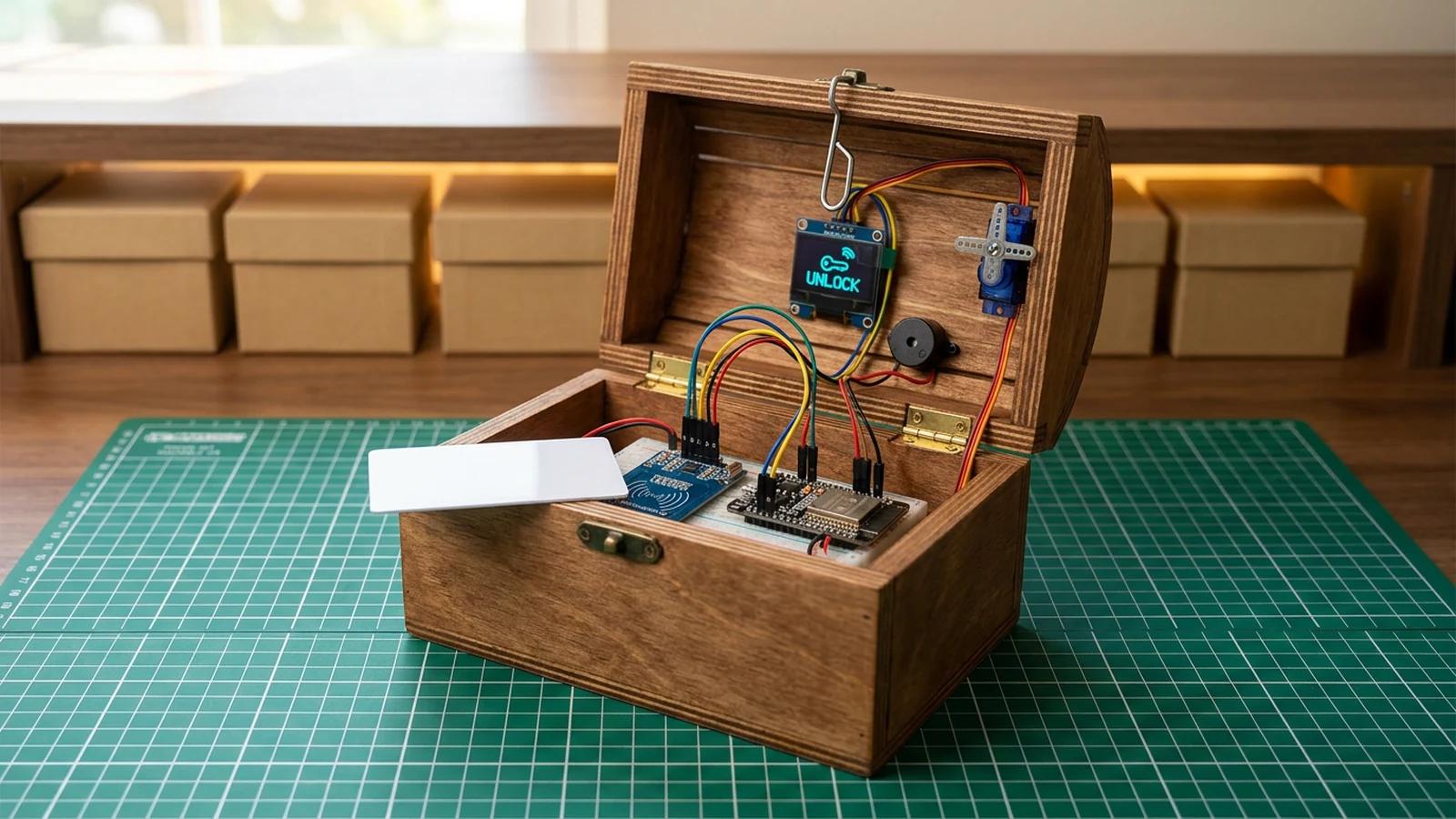
How to Build an RFID Treasure Chest with ESP32
Design an ESP32 RFID treasure chest with MFRC522 reader, servo lock, buzzer, and OLED. Valid tags unlock the chest with a success tune.