On this page
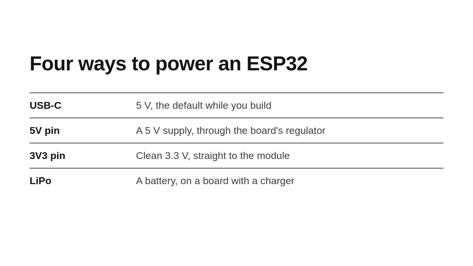
An ESP32 can run from a laptop's USB port, a phone charger, a bench supply or a battery the size of a postage stamp. Each of those goes into the board through a different door, and the door decides what voltage you can use and what protects the chip.
This guide follows each path through a real board, the Espressif ESP32-S3-DevKitC-1, the board in the Schematik Starter Kit. The kit's version has two USB-C ports where Espressif's own board has Micro-USB, but the power paths are the same. The numbers come from the datasheets of the parts on it: the ESP32-S3-WROOM-1 module, the SGM2212 regulator and the 1N5819HW diode.
One rule first, straight from Espressif's user guide: the three ways to power this board (USB, the 5V pin and the 3V3 pin) are mutually exclusive. Use one at a time.
What the ESP32 needs
The ESP32-S3 module runs on 3.3 V. Its datasheet allows 3.0 to 3.6 V, and asks for a supply that can deliver at least 0.5 A. That sounds like a lot for a chip that idles at a few tens of milliamps, but Wi-Fi transmits in short bursts of up to 355 mA, and a supply that sags during a burst makes the chip reset. A sudden reboot every time it connects to Wi-Fi is the classic sign of a weak supply.
So every power path below ends the same way: a steady 3.3 V with current to spare.
Powering an ESP32 over USB

USB is the default, and the one to use while you are building. Plug a USB-C cable into either port and the board does the rest.
Each USB port passes through a Schottky diode, a one-way valve for current that only costs a small voltage drop: at most 0.32 V at 100 mA and 0.45 V at 1 A. The diodes stop the two ports, or the 5V pin, from pushing current back into your computer.
What is left, about 4.5 V from a 5 V port, goes into the regulator. A regulator turns a higher, wobbly voltage into a steady lower one. This one is an SGM2212 LDO, short for low-dropout regulator: it keeps working until its input falls to within 0.38 V of its output at 500 mA, so 4.5 V leaves plenty of room. It holds 3.3 V within 1.5% and is rated for up to 800 mA, enough headroom for the module's 0.5 A.
Powering an ESP32 from the 5V pin

Use the 5V pin when the board lives inside a project with its own 5 V supply, like a USB power bank wired to a terminal block, or a 5 V supply that also runs an LED strip. Connect the supply's positive wire to 5V and its negative wire to GND.
The 5V pin joins the board after the diodes, so it feeds the regulator directly, and the diodes keep it from back-feeding the USB ports. Everything after that is the same as USB.
Stick to a regulated 5 V. A 9 V battery or a 12 V adapter makes the regulator burn the difference as heat: at 200 mA from 12 V, it would turn about 1.7 W into heat in a package the datasheet rates at 117 °C per watt, enough to trip its thermal shutdown.
Powering an ESP32 from the 3V3 pin

The 3V3 pin skips the regulator and goes straight to the module. That makes it the most efficient path and the least forgiving one. Your supply has to stay between 3.0 and 3.6 V and deliver at least 0.5 A, because nothing on the board will clean it up.
Use it when you already have a good 3.3 V source, like a buck converter (a switching regulator that wastes far less power than an LDO) on a larger project board. Do not feed it straight from a LiPo cell: a full cell sits at 4.2 V, above the module's 3.6 V limit.
Do not connect the 3V3 pin and USB at the same time. Your supply and the board's regulator would fight over the same wire.
Running an ESP32 on a LiPo battery

A LiPo is the flat, rechargeable lithium battery inside phones and earbuds. The DevKitC-1 has no battery connector or charger, so for a battery build, pick a board that has both. The charger refills the cell safely from USB-C, and the board's own regulator turns the cell's voltage into 3.3 V.
The Seeed Studio XIAO ESP32S3 is a good example. Its documentation asks for a 3.7 V rechargeable lithium cell soldered to the battery pads on the back: negative on the side nearest the USB port, positive on the far side. The same USB-C port that flashes the board then charges the battery, and a red light flashes while it does. The LilyGo T-Display in the digital hair clip works the same way with a Micro JST 1.25 mm plug instead of pads.
The e-ink photo camera runs two boards this way, each on its own LiPo, with no wires between them at all.
Deep sleep: making a battery last
Battery life comes down to what the board draws while it is doing nothing, because a sensor that reads once every 10 minutes spends almost all its time doing nothing.
Deep sleep switches off everything except the real-time clock and a little memory. The ESP32-S3 datasheet puts the chip at a typical 7 µA in deep sleep, against 66 to 108 mA with both cores busy at 240 MHz. That is roughly 10,000 times less.
The catch is that a sleeping chip is not a sleeping board. Here are some of the parts still powered on a DevKitC-1:
| Part | Draw while the ESP32 sleeps | Source |
|---|---|---|
| ESP32-S3 in deep sleep | 7 µA | ESP32-S3 datasheet |
| SGM2212 regulator, no load | 80 µA typical | SGM2212 datasheet |
| Red power LED on a 5.1 kΩ resistor | About 0.25 mA (3.3 V less the LED's 2.0 V, across 5.1 kΩ) | Board parts list, LED datasheet |
The USB-to-serial chip and the RGB LED sit on the same 3.3 V line too. The regulator alone draws more than 10 times what the sleeping chip does, so a DevKitC-1 on a battery spends most of its charge on things that are not the ESP32. For a battery build, the board matters more than the chip: Seeed lists 14 µA for the whole XIAO ESP32S3 in deep sleep.
Here is what that buys you. Say a XIAO wakes for 2 seconds every 10 minutes at the 100 mA Seeed lists for it with Wi-Fi on, and sleeps the rest of the time at 14 µA. That averages out to about 0.35 mA, so a 1,000 mAh LiPo lasts roughly four months on paper. Make the wake shorter and it lasts longer; leave Wi-Fi on all the time and it is about 10 hours.
Giuseppe Faccilongo's Zigbee Temperature Humidity Sensor takes this to the extreme: an ESP32-C6 that wakes, reports and goes back to sleep on a single CR2450 coin cell.
Start building
Building on the DevKitC-1? Power it over USB and forget about it. Building something that runs on a battery? Pick a board with a charger, and use deep sleep from day one. Either way, open Schematik, name your board and describe what you want to make. It picks the pins and writes the code, including the deep-sleep loop.
Keep building from here
Jump into a step-by-step build, or open Schematik and turn your own idea into code, wiring, and assembly instructions.
Related posts
New to Hardware? A Beginner ESP32 Guide for Your First Build
A beginner ESP32 hardware guide: what to buy first, how breadboards work, what pin labels mean, and what to check before powering your first build.
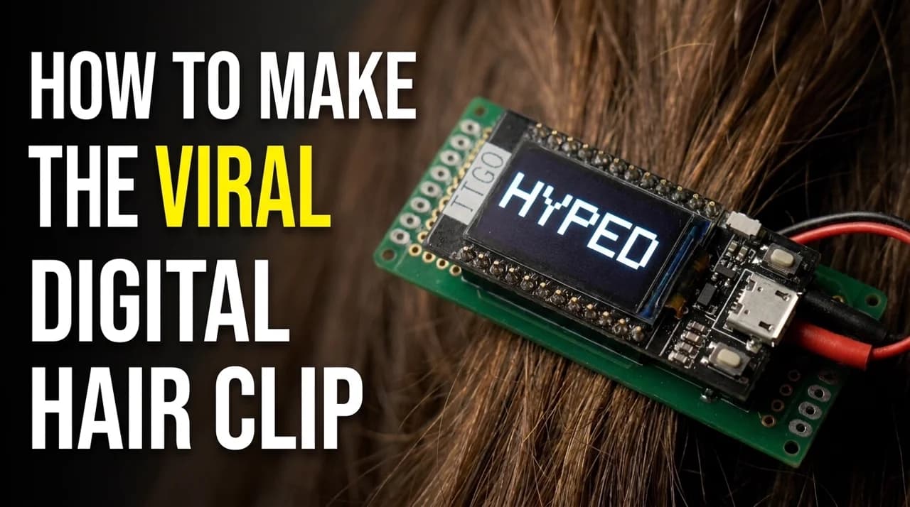
How to Make the Viral Digital Hair Clip
A LilyGo T-Display clipped into your hair, showing whatever you want it to say. Four parts, no breadboard, and the soldering is optional. The hard bit is not the electronics, it is getting it to stay on your head.

How to Build an E-Ink Camera
A XIAO ESP32S3 Sense in a 3D-printed shell takes a photo and pushes the JPEG over ESP-NOW to an M5Stack PaperColor, where it lands on the e-ink screen. No router, no SD card, no phone.
Related builds
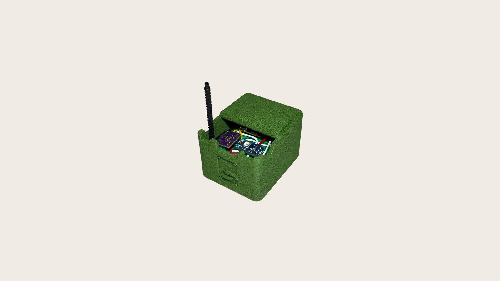
UV Weather Alert Station
Build a portable UV weather station with ESP32, BME280, and UV sensor for sun safety monitoring.
E-Ink Photo Camera
Build a wireless e-ink photo camera using ESP32, XIAO camera module, and M5Paper display with ESP-NOW.

How to Build a Fitness Wristband Prototype with ESP32
Build an ESP32 fitness wearable prototype with MAX30102 heart-rate sensor, MPU6050 motion tracking, and OLED. Includes complete code and wiring guide.