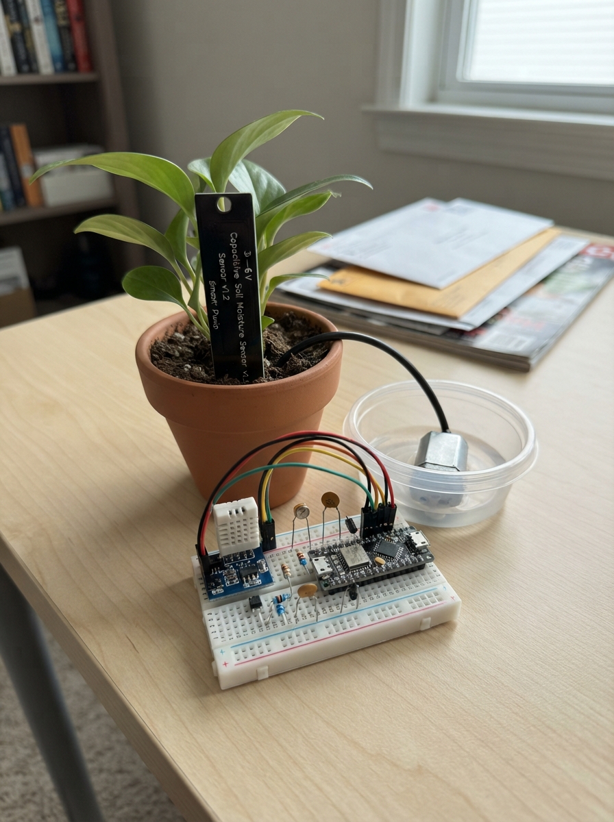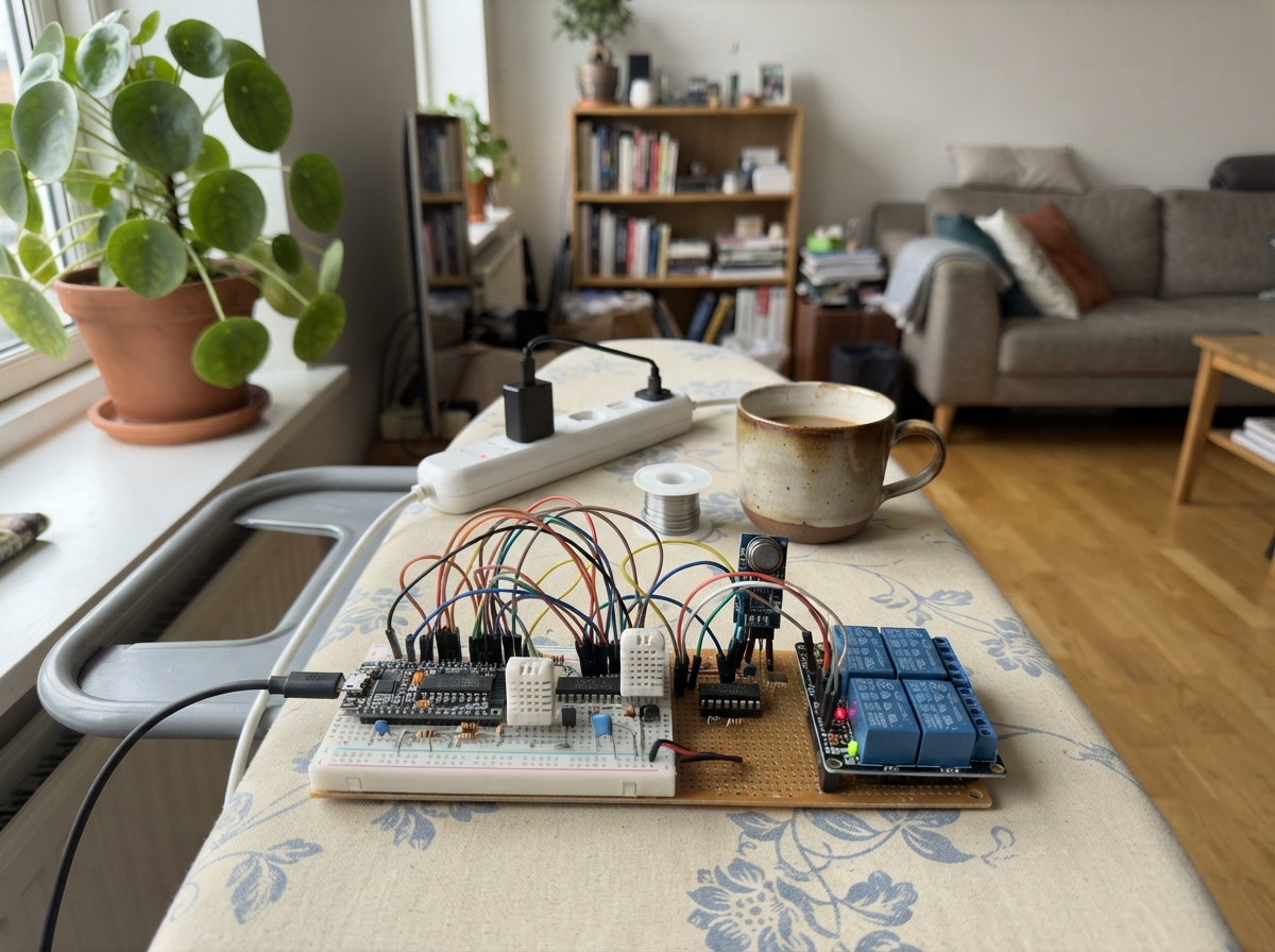
This 16-channel home automation system uses an ESP32 microcontroller to control lights, fans, air conditioning, and other household devices over WiFi. Built around an MCP23017 I/O expander, a relay module, and sensor inputs for temperature, humidity, and gas detection, the system provides web-based control with real-time monitoring of environmental conditions.
The guide includes a complete wiring diagram showing how to connect the I/O expander, relay drivers, DHT22 sensor, and gas sensor to the ESP32, along with a parts list, Arduino firmware with a web interface, and step-by-step assembly instructions. All work is performed on low-voltage circuits with household electricity safely disconnected.
Wiring diagram
Gather all the parts
Assemble it in 5 steps
1. Keep household electricity disconnected
Build and test only the low-voltage controller first. Channels 1-10 are lights, 11-12 are fans, 13 is AC enable, and 14-16 are spare. Fan control is on/off only.
- Never put household mains on a breadboard. A qualified electrician must select protection and enclosed appliance wiring. Do not switch an AC compressor directly with these hobby relays; use an appropriately rated professionally installed contactor or an approved low-voltage enable input.
2. Wire the expander
Use the DIP-28 MCP23017. VDD pin 9 goes to 3V3, VSS pin 10 to ground, SDA pin 13 to GPIO21 for data, SCL pin 12 to GPIO22 for clock. Ground A0/A1/A2 pins 15/16/17 and connect RESET pin 18 to 3V3. Put the 100nF capacitor across pins 9 and 10. Each data/clock line gets a 4.7k resistor to 3V3.
3. Add the relay input drivers
Use two ULN2803A DIP-18 chips. Inputs 1-8 are physical pins 1-8, GND is pin 9, COM is pin 10, and outputs 1-8 are physical pins 18 down to 11. GPA0-GPA7 (MCP pins 21-28) drive the first chip; GPB0-GPB7 (pins 1-8) drive the second. Each driver input gets its own 10k resistor to ground. Connect each driver output to the matching IN1-IN8 relay input. HIGH expander outputs turn the low-trigger relays on.
- Use exactly the selected 5V low-trigger modules; verify each channel clicks only when commanded ON before attaching any load.
4. Connect the sensors
DHT22 VCC goes to 3V3, GND to ground, DATA to GPIO4 with a 10k pull-up to 3V3. MQ-2 VCC goes to the separate 5V supply. Its AO goes through a 10k resistor to GPIO32; a second 10k resistor connects GPIO32 to ground. Leave DO disconnected. This divider limits a 5V output to 2.5V.
- MQ-2 is experimental and cannot replace a certified gas alarm. Initial conditioning may require 24-48 hours following the sensor instructions; the three-minute firmware warm-up is not calibration. Do not operate switches or relays if a gas leak is suspected.
5. Power the low-voltage circuit
Use the regulated 5V 4A adapter with a suitable output breakout lead for the two relay modules and gas heater. Keep relay supply positive separate from ESP32 USB power. Connect all grounds together. Power the ESP32 by USB. Use a soldered low-voltage board and insulated enclosure after testing.
- Do not feed relay coil current through the ESP32 or breadboard rails. Never connect external 5V to ESP32 while USB is attached in this design.
Review all connections
1. Connections between "exp" and "ESP32"
2. Connections between "dht" and "ESP32"
3. Connections between "gas" and "ESP32"
4. Connections between "supply" and "ESP32"
5. Connections between "relay1" and "ESP32"
6. Connections between "driver1" and "ESP32"
7. Connections between "pulldown1" and "ESP32"
8. Connections between "pulldown2" and "ESP32"
9. Connections between "pulldown3" and "ESP32"
10. Connections between "pulldown4" and "ESP32"
11. Connections between "pulldown5" and "ESP32"
12. Connections between "pulldown6" and "ESP32"
13. Connections between "pulldown7" and "ESP32"
14. Connections between "pulldown8" and "ESP32"
15. Connections between "relay2" and "ESP32"
16. Connections between "driver2" and "ESP32"
17. Connections between "pulldown9" and "ESP32"
18. Connections between "pulldown10" and "ESP32"
19. Connections between "pulldown11" and "ESP32"
20. Connections between "pulldown12" and "ESP32"
21. Connections between "pulldown13" and "ESP32"
22. Connections between "pulldown14" and "ESP32"
23. Connections between "pulldown15" and "ESP32"
24. Connections between "pulldown16" and "ESP32"
25. Connections between "dhtpull" and "ESP32"
26. Connections between "sdapull" and "ESP32"
27. Connections between "sclpull" and "ESP32"
28. Connections between "gastop" and "ESP32"
29. Connections between "gasbottom" and "ESP32"
30. Connections between "decouple" and "ESP32"
Deploy the firmware
#include <Arduino.h>
#include <WiFi.h>
#include <WebServer.h>
#include <Wire.h>
#include <Adafruit_MCP23X17.h>
#include <DHT.h>
WebServer server(80);
Adafruit_MCP23X17 expander;
DHT dht(4,DHT22);
const char* PASSWORD="HomeControl16!"; // Change before deploying in a home.
const char* names[16]={"Light 1","Light 2","Light 3","Light 4","Light 5","Light 6","Light 7","Light 8","Light 9","Light 10","Fan 1","Fan 2","AC enable","Spare 1","Spare 2","Spare 3"};
uint16_t outputs=0; bool ready=false; float temp=NAN, humidity=NAN; int gasRaw=0;
unsigned long sensorTime=0, acOff=0;
const unsigned long AC_DELAY=180000;
const int GAS_THRESHOLD=2400; // Demonstration threshold, NOT a calibrated gas alarm.
const char page[] PROGMEM=R"HTML(<!doctype html><meta name="viewport" content="width=device-width,initial-scale=1"><title>Home control</title><style>body{font:18px sans-serif;max-width:650px;margin:20px}button{padding:12px;margin:5px}section{border-bottom:1px solid #ccc;padding:5px}</style><h1>16-channel home control</h1><p id="s">Loading...</p><p>Gas readings are experimental. Use a certified gas alarm.</p><div id="channels"></div><button onclick="alloff()">All OFF</button><p id="msg"></p><script>
async function refresh(){let s=await(await fetch('/status')).json();document.getElementById('s').textContent='Temperature: '+s.temperature+' C | Humidity: '+s.humidity+' % | Gas raw: '+s.gas+' | '+s.gasState+' | AC wait: '+s.acWait+' s';let d=document.getElementById('channels');if(!d.children.length)s.names.forEach((n,i)=>{let x=document.createElement('section');x.innerHTML=n+' <span id="v'+i+'"></span> <button onclick="set('+i+',1)">ON</button><button onclick="set('+i+',0)">OFF</button>';d.appendChild(x)});s.states.forEach((v,i)=>document.getElementById('v'+i).textContent=v?'ON':'OFF')}
async function set(i,on){let r=await fetch('/set',{method:'POST',headers:{'Content-Type':'application/x-www-form-urlencoded'},body:'ch='+i+'&on='+on});document.getElementById('msg').textContent=await r.text();refresh()}
async function alloff(){await fetch('/off',{method:'POST'});refresh()}refresh();setInterval(refresh,2500);
</script>)HTML";
bool authorized(){if(server.authenticate("admin",PASSWORD))return true;server.requestAuthentication();return false;}
unsigned long acWait(){unsigned long elapsed=millis()-acOff;return elapsed>=AC_DELAY?0:(AC_DELAY-elapsed+999)/1000;}
void writeOutputs(){if(ready)expander.writeGPIOAB(outputs);}
void allOff(){if(outputs&(1u<<12))acOff=millis();outputs=0;writeOutputs();}
void status(){if(!authorized())return;String j="{\"temperature\":";j+=isnan(temp)?"null":String(temp,1);j+=",\"humidity\":";j+=isnan(humidity)?"null":String(humidity,1);j+=",\"gas\":"+String(gasRaw)+",\"gasState\":\"";j+=millis()<180000?"WARMING UP":(gasRaw>=GAS_THRESHOLD?"HIGH - investigate safely":"experimental reading");j+="\",\"acWait\":"+String(acWait())+",\"names\":[";for(int i=0;i<16;i++){if(i)j+=",";j+="\""+String(names[i])+"\"";}j+="],\"states\":[";for(int i=0;i<16;i++){if(i)j+=",";j+=String((outputs>>i)&1);}j+="]}";server.send(200,"application/json",j);}
void setup(){Serial.begin(115200);Wire.begin(21,22);Wire.setTimeOut(100);ready=expander.begin_I2C(0x20);if(ready){expander.writeGPIOAB(0);for(int i=0;i<16;i++)expander.pinMode(i,OUTPUT);}dht.begin();analogReadResolution(12);analogSetPinAttenuation(32,ADC_11db);acOff=millis();WiFi.softAP("HomeControl-16",PASSWORD);Serial.println(WiFi.softAPIP());server.on("/",HTTP_GET,[]{if(authorized())server.send_P(200,"text/html",page);});server.on("/status",HTTP_GET,status);server.on("/off",HTTP_POST,[]{if(!authorized())return;allOff();server.send(200,"text/plain","All channels OFF");});server.on("/set",HTTP_POST,[]{if(!authorized())return;if(!ready){server.send(503,"text/plain","Expander missing; check wiring and reboot");return;}String c=server.arg("ch"),v=server.arg("on");int ch=c.toInt();if(c!=String(ch)||ch<0||ch>15||(v!="0"&&v!="1")){server.send(400,"text/plain","Invalid command");return;}bool on=v=="1";if(ch==12&&on&&!(outputs&(1u<<12))&&acWait()){server.send(409,"text/plain","AC restart delay: wait "+String(acWait())+" seconds");return;}if(ch==12&&!on&&(outputs&(1u<<12)))acOff=millis();if(on)outputs|=(1u<<ch);else outputs&=~(1u<<ch);writeOutputs();server.send(200,"text/plain","Command applied");});server.begin();}
void loop(){server.handleClient();if(millis()-sensorTime>=2500){sensorTime=millis();temp=dht.readTemperature();humidity=dht.readHumidity();gasRaw=analogRead(32);}delay(2);}
Remix this project
Make it yours in one click
Open a full copy of this project in your own Schematik workspace, diagram, code, parts, and assembly steps included. Swap the sensor, add features, or redesign the whole thing with AI. The author's original stays untouched.