This soccer scoreboard project turns an ESP32 microcontroller into a dedicated scoring display for 20cm drone soccer matches. The setup uses a small SSD1306 OLED screen to show real-time scores for two teams, with push buttons wired to increment points and reset the board.
The guide provides a complete wiring diagram, parts list, and step-by-step assembly instructions for connecting the OLED display and control buttons to the ESP32. Builders will also receive the Arduino firmware that handles debounced button inputs, score tracking with a two-second reset hold, and formatted score display on the screen.
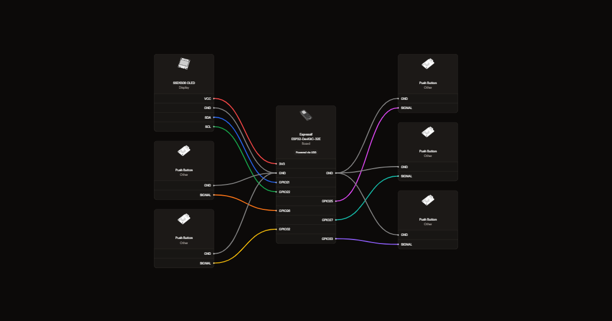
Wiring diagram
Gather all the parts
Assemble it in 5 steps
1. Préparer le montage hors tension
Préparez un ESP32-DevKitC-32E, un écran OLED SSD1306 I2C 128 × 64 à quatre broches et cinq boutons poussoirs momentanés. Utilisez des fils de connexion et une plaque de montage sans soudure. Débranchez le câble USB avant le câblage.
2. Brancher le petit écran
VCC → 3V3 (alimentation), GND → GND (retour du courant), SDA → GPIO21 (données), SCL → GPIO22 (horloge de communication).
- Vérifiez les inscriptions VCC et GND sur votre écran : leur position varie. Une inversion peut endommager le module.
3. Brancher les commandes des équipes
Chaque bouton relie son contact SIGNAL à une entrée et son autre contact à GND. Plus A → GPIO25, plus B → GPIO26, moins A → GPIO27, moins B → GPIO32. Les résistances internes de l’ESP32 sont activées par le programme.
- Sur un bouton à quatre pattes, deux pattes sont déjà reliées entre elles. Choisissez deux contacts qui ne se rejoignent que lorsque vous appuyez.
- Étiquetez les boutons A +, B +, A − et B −.
4. Ajouter la remise à zéro
Branchez SIGNAL du dernier bouton à GPIO33 et GND à GND. Étiquetez-le RAZ. Un maintien de deux secondes remet les deux scores à zéro.
5. Vérifier et protéger le tableau
Contrôlez tous les fils avant d’alimenter par USB. Fixez ensuite le montage dans un boîtier, hors de la zone de vol. L’écran de 0,96 pouce se lit de près : cette version sert à la table de marque, pas à l’affichage pour le public.
- Les scores vont de 0 à 99. Une coupure d’alimentation remet les scores à zéro.
Review all connections
1. Connections between "oled" and "ESP32"
2. Connections between "plusA" and "ESP32"
3. Connections between "plusB" and "ESP32"
4. Connections between "moinsA" and "ESP32"
5. Connections between "moinsB" and "ESP32"
6. Connections between "reset" and "ESP32"
Deploy the firmware
#include <Arduino.h>
#include <Wire.h>
#include <Adafruit_GFX.h>
#include <Adafruit_SSD1306.h>
Adafruit_SSD1306 screen(128,64,&Wire,-1);
const uint8_t pins[] = {25,26,27,32,33};
bool raw[5]={}, stable[5]={};
unsigned long changed[5]={}, resetSince=0;
bool resetDone=false;
uint8_t score[2]={0,0};
void drawScore(){
 screen.clearDisplay(); screen.setTextColor(SSD1306_WHITE);
 screen.setTextSize(1); screen.setCursor(0,0); screen.print(F("EQUIPE A   EQUIPE B"));
 screen.setTextSize(3); screen.setCursor(3,20);
 if(score[0]<10) screen.print('0'); screen.print(score[0]);
 screen.setCursor(57,20); screen.print('-'); screen.setCursor(87,20);
 if(score[1]<10) screen.print('0'); screen.print(score[1]);
 screen.setTextSize(1); screen.setCursor(0,55); screen.print(F("RAZ : maintenir 2 s")); screen.display();
}
void setup(){
 Serial.begin(9600);
 for(uint8_t i=0;i<5;i++) pinMode(pins[i],INPUT_PULLUP);
 Wire.begin(21,22);
 delay(500);
 if(!screen.begin(SSD1306_SWITCHCAPVCC,0x3C)){Serial.println(F("Erreur ecran"));while(true) delay(100);}
 drawScore();
}
void loop(){
 unsigned long now=millis(); bool dirty=false;
 for(uint8_t i=0;i<5;i++){
  bool down=digitalRead(pins[i])==LOW;
  if(down!=raw[i]){raw[i]=down; changed[i]=now;}
  if(now-changed[i]>=35 && stable[i]!=raw[i]){
   stable[i]=raw[i];
   if(i==4){if(stable[i]){resetSince=now;resetDone=false;}}
   else if(stable[i] && !stable[4]){
    uint8_t team=i%2, before=score[team];
    if(i<2){if(score[team]<99)score[team]++;}
    else if(score[team]>0)score[team]--;
    dirty |= before!=score[team];
   }
  }
 }
 if(stable[4] && !resetDone && now-resetSince>=2000){
  dirty |= score[0]!=0 || score[1]!=0;
  score[0]=score[1]=0; resetDone=true;
 }
 if(dirty)drawScore();
}
Remix this project
Make it yours in one click
Open a full copy of this project in your own Schematik workspace, diagram, code, parts, and assembly steps included. Swap the sensor, add features, or redesign the whole thing with AI. The author's original stays untouched.