Community project
Arduino LED Blinker
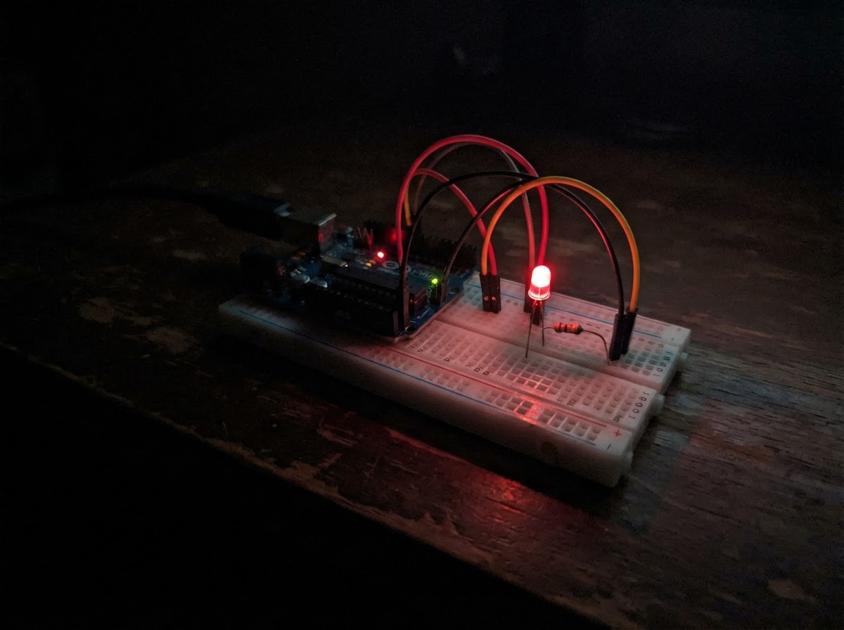
This project demonstrates the fundamentals of controlling an external LED with an Arduino Uno microcontroller. The LED blinks on and off at regular intervals, providing a simple yet effective introduction to digital output control and basic circuit design.
The guide includes a complete wiring diagram showing how to connect the LED and current-limiting resistor to the Uno, a parts list, step-by-step assembly instructions, and the Arduino sketch needed to make the LED blink. This is an ideal starting point for anyone new to microcontroller programming and electronics prototyping.
Wiring diagram

Gather all the parts
Assemble it in 4 steps
1. Place the LED
Insert the LED into a breadboard. Identify its long lead as the anode (+) and its short lead, usually beside the flat edge of the LED body, as the cathode (−).
- Keep the two LED leads in separate breadboard rows.
- Reversing the LED prevents it from lighting.
2. Add the current-limiting resistor
Connect one end of the 220 Ω resistor to the LED anode (long lead). Connect the other resistor end to Arduino Uno digital pin D8.
- A 220 Ω resistor commonly has red-red-brown-gold color bands.
- The resistor has no polarity, so either end may face D8.
- Do not connect the LED directly to D8 without the resistor; that can overload the LED or Arduino pin.
3. Connect the LED return
Connect the LED cathode (short lead/flat side) to any GND pin on the Arduino Uno.
- Use a black jumper wire for the ground connection if available.
- All connections should be made with the Uno unplugged from USB.
4. Power the Uno
After checking the three connections—D8 → resistor → LED anode and LED cathode → GND—connect the Arduino Uno to your computer with USB. Use Schematik’s Deploy button to compile and flash the project.
- The external LED will turn on for one second and off for one second repeatedly.
- If it does not blink, unplug USB and recheck LED orientation and that D8, not D13, is used.
Review all connections
1. Connections between "resistor_1" and "Arduino"
2. Connections between "led_1" and "Arduino"
Deploy the firmware
#include <Arduino.h>
// Arduino Uno external LED blink
// LED anode is connected to D8 through a 220 ohm resistor.

constexpr uint8_t LED_PIN = 8;
constexpr unsigned long BLINK_INTERVAL_MS = 1000;

bool ledOn = false;
unsigned long lastToggleMs = 0;

void setup() {
  pinMode(LED_PIN, OUTPUT);
  digitalWrite(LED_PIN, LOW);
}

void loop() {
  const unsigned long now = millis();
  if (now - lastToggleMs >= BLINK_INTERVAL_MS) {
    lastToggleMs = now;
    ledOn = !ledOn;
    digitalWrite(LED_PIN, ledOn ? HIGH : LOW);
  }
}
Remix this project
Make it yours in one click
Open a full copy of this project in your own Schematik workspace — diagram, code, parts, and assembly steps included. Swap the sensor, add features, or redesign the whole thing with AI. The author's original stays untouched.
Related projects
Necesito Hacer Un Circuito De Un Oxiometro Con
Arduino · September 25, 2026MARIA PAULA LAMBOGLIA VARGAS
Laser Harp Instrument
Arduino · September 25, 2026juliasualoka2
Três Sensores de Luz
Arduino · September 25, 2026arthur.brazil