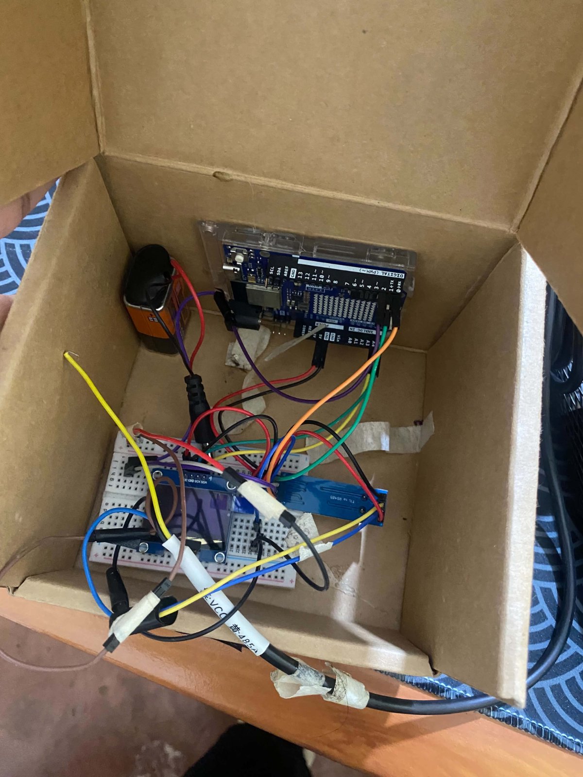
This project builds a Total Suspended Solids (TSS) monitor using an Arduino Uno and the DFRobot Gravity Analog Turbidity Sensor. The turbidity probe measures light transmission through water to estimate suspended particle concentration, with results displayed on a 16×2 LCD screen in real time. The guide includes a complete wiring diagram, parts list, and step-by-step assembly instructions for connecting the optical sensor and display.
The firmware provided reads analog voltage from the turbidity sensor and can be calibrated against laboratory-measured TSS samples to produce meaningful mg/L estimates. Makers will learn how to wire I2C displays, handle analog sensor input on the Uno, and implement a two-point calibration method to convert raw sensor readings into quantitative water quality data. The guide covers inspection checkpoints, initial testing procedures, and best practices for taking repeatable measurements.
Wiring diagram
Gather all the parts
Assemble it in 9 steps
1. Disconnect power and identify the parts
Unplug USB and disconnect the pictured 9 V battery, including its barrel plug. This guide is for the saved Uno project with a SEN0189 turbidity probe and adapter plus a four-pin I2C 16x2 LCD. The overlapping wires in the photo cannot be verified; check every connection by its printed label before reusing it.
- A pH probe cannot measure suspended solids. Do not connect an unidentified probe as though it were a SEN0189.
- Never connect the 9 V battery to a 5V pin or module supply; this can destroy the electronics. Leave it disconnected for this USB-powered build.
2. Arrange a dry work area
Place the Uno, LCD and sensor adapter on a stable dry surface above and away from the water sample. Keep the sample outside the cardboard box shown in the photo. Arrange the wires so moving the sample cannot pull the electronics into water.
- Cardboard is not waterproof. Wet electronics can short circuit; keep all exposed connections away from splashes.
3. Connect the probe to its adapter
Use the complete SEN0189 kit. Plug its supplied optical probe into the matching adapter connector using the supplied cable. Set the adapter D/A switch to A for analog measurement.
- The adapter's threshold adjustment affects digital mode; it does not calibrate TSS.
4. Wire sensor power and measurement
With power still disconnected, connect adapter VCC to Uno 5V (power), adapter GND to Uno GND (ground), and adapter SIGNAL or S to Uno A0 (measurement). Follow the labels on the adapter, not wire colours.
- Reversing VCC and GND can damage the adapter. Check the labels at both ends of each wire.
5. Wire the four-pin LCD
Use the LCD with a PCF8574 I2C adapter at address 0x27. Connect LCD VCC to Uno 5V (power), GND to Uno GND (ground), SDA to A4 (data), and SCL to A5 (clock). The LCD and sensor share the same 5V and ground supplies.
- If sharing power through the pictured breadboard, connect Uno 5V to its positive rail and GND to its negative rail, then connect both modules to those same continuous rail sections. Some rails have a gap in the middle.
- A bare screen with 16 connector pins is not the four-wire version this project expects. Do not guess its connections.
6. Inspect every connection before USB power
Trace these seven module connections one by one: sensor VCC to 5V, sensor GND to GND, sensor SIGNAL to A0, LCD VCC to 5V, LCD GND to GND, LCD SDA to A4, LCD SCL to A5. Check for loose wire ends, exposed contacts touching each other, and wires inserted in the wrong breadboard row. Keep the battery disconnected.
- Disconnect power again before correcting any wire. A short between 5V and GND can damage or overheat the wiring.
7. Position the optical sensing section
Place only the probe's lower sensing section in the sample. Keep its top, connector, adapter, screen and Uno dry. Keep the optical gap clear of the cup wall, sediment deposits and bubbles. Use a repeatable immersion depth.
- The probe top is not waterproof. Do not fully submerge the probe or leave this assembly permanently underwater.
8. Check the screen during initial testing
Once wiring is checked, USB is the only power source for this build. With the project firmware running, expect Signal ADC and TSS: calibrate after startup. Gently adjust the LCD adapter's contrast screw if the backlight is on but text is hard to see. If Check sensor appears, disconnect power and inspect the sensor wiring and probe connection.
- A blank screen can also mean the LCD adapter is not at the expected address 0x27. Do not move wires while powered.
9. Take repeatable samples and plan calibration
Gently mix each sample to keep solids suspended, remove bubbles from the sensing gap, and measure at consistent depth, lighting and temperature. Rinse the sensing section between samples. Record stable ADC readings alongside laboratory-tested TSS results from representative samples; two points support a rough linear estimate, and additional samples are needed to check it.
- Until calibrated, this build measures a cloudiness signal, not TSS in mg/L. Different particle types require new calibration.
- Even after calibration it is a sample-specific estimate within the checked range, not a laboratory TSS instrument or a drinking-water safety tester.
Review all connections
1. Connections between "turbidity" and "Arduino"
2. Connections between "lcd" and "Arduino"
Deploy the firmware
#include <Arduino.h>
#include <Wire.h>
#include <LiquidCrystal_PCF8574.h>
#include <string.h>
LiquidCrystal_PCF8574 lcd(0x27);
bool screenPresent = false;
char previous[2][17] = {};
void showLine(uint8_t row, const char *text) {
  if (!screenPresent) return;
  char padded[17]; memset(padded, ' ', 16); padded[16] = 0;
  strncpy(padded, text, min((size_t)16, strlen(text)));
  if (strcmp(previous[row], padded)) {
    lcd.setCursor(0, row); lcd.print(padded);
    strcpy(previous[row], padded);
  }
}


// This is an optical proxy, NOT a direct TSS or certified NTU measurement.
// To enable approximate TSS: obtain two representative samples with TSS
// measured by a laboratory filtration/drying method. Record their mean ADC
// readings here, along with their lab mg/L values. Then set CALIBRATED true.
// Validate against additional samples. Only interpolate; do not extrapolate.
constexpr bool CALIBRATED = false;
constexpr float SAMPLE_1_ADC = 0.0f; // Replace: measured ADC for lower TSS
constexpr float SAMPLE_1_MG_L = 0.0f; // Replace: laboratory result
constexpr float SAMPLE_2_ADC = 0.0f; // Replace: measured ADC for higher TSS
constexpr float SAMPLE_2_MG_L = 0.0f; // Replace: laboratory result
constexpr uint8_t SENSOR_PIN = A0;
constexpr float ADC_REFERENCE_V = 5.0f; // Nominal USB-powered Uno supply

void setup() {
  Serial.begin(9600);
  Wire.begin();
  Wire.beginTransmission(0x27);
  screenPresent = Wire.endTransmission() == 0;
  if (screenPresent) { lcd.begin(16, 2, Wire); lcd.setBacklight(255); }
  else Serial.println(F("LCD not found at 0x27; check wiring/address."));
  showLine(0, "Solids monitor");
  showLine(1, "Starting...");
  analogReference(DEFAULT);
  pinMode(SENSOR_PIN, INPUT);
  Serial.println(F("Suspended-solids optical estimator"));
  Serial.println(F("Uncalibrated = cloudiness signal only, not mg/L or NTU."));
  Serial.println(F("Keep probe top and electronics dry. Not a drinking-water safety test."));
  // Allow the optical sensor to settle before collecting the first sample.
  delay(2000);
  analogRead(SENSOR_PIN); // Discard the first ADC conversion.
}

void loop() {
  uint32_t sum = 0;
  for (uint8_t i = 0; i < 64; ++i) {
    sum += analogRead(SENSOR_PIN);
    delay(5);
  }
  const float adc = sum / 64.0f;
  char line[17];
  snprintf(line, sizeof(line), "Signal ADC: %4u", (unsigned)(adc + 0.5f));
  showLine(0, line);
  Serial.print(F("ADC=")); Serial.print(adc, 1);
  Serial.print(F(" | voltage~"));
  Serial.print(adc * ADC_REFERENCE_V / 1024.0f, 3);
  Serial.print(F(" V | "));
  if (adc < 10 || adc > 1000) {
    showLine(1, "Check sensor");
    Serial.println(F("CHECK SENSOR: near ADC limit; inspect wiring and probe."));
  } else if (!CALIBRATED) {
    showLine(1, "TSS: calibrate");
    Serial.println(F("TSS unavailable: needs sample-specific lab calibration"));
  } else if (SAMPLE_1_ADC <= SAMPLE_2_ADC + 5.0f ||
             SAMPLE_1_MG_L < 0 || SAMPLE_2_MG_L <= SAMPLE_1_MG_L) {
    showLine(1, "Bad calibration");
    Serial.println(F("Invalid calibration: use separated points, voltage falling as TSS rises."));
  } else if (adc > SAMPLE_1_ADC || adc < SAMPLE_2_ADC) {
    showLine(1, "Outside range");
    Serial.println(F("Outside calibrated range: TSS unavailable"));
  } else {
    float tss = SAMPLE_1_MG_L + (adc - SAMPLE_1_ADC) *
        (SAMPLE_2_MG_L - SAMPLE_1_MG_L) / (SAMPLE_2_ADC - SAMPLE_1_ADC);
    if (tss <= 999999.0f) {
      char number[12]; dtostrf(tss, 1, 1, number);
      snprintf(line, sizeof(line), "%s mg/L est", number);
      showLine(1, line);
    } else showLine(1, "TSS too large");
    Serial.print(F("Estimated TSS=")); Serial.print(tss, 1);
    Serial.println(F(" mg/L (sample-specific linear estimate)"));
  }
  delay(700);
}
Remix this project
Make it yours in one click
Open a full copy of this project in your own Schematik workspace, diagram, code, parts, and assembly steps included. Swap the sensor, add features, or redesign the whole thing with AI. The author's original stays untouched.