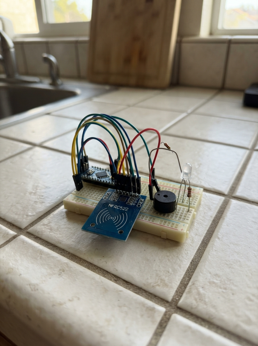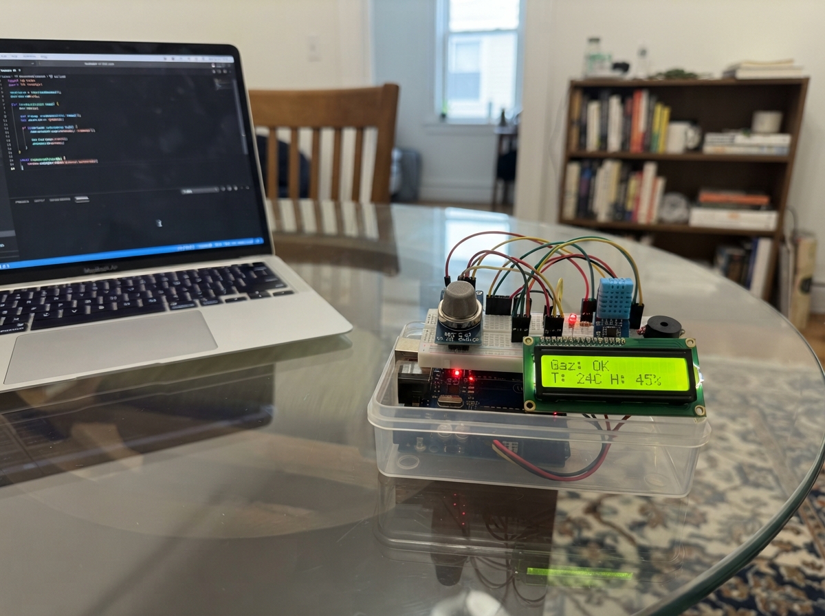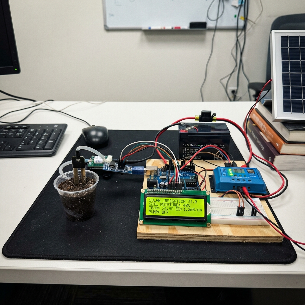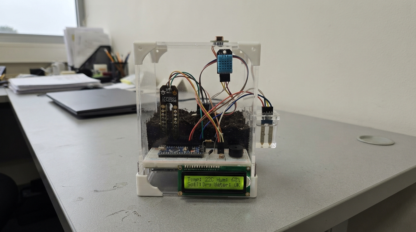
This automated mini greenhouse uses an Arduino Uno to monitor and control growing conditions for small plants. The system reads soil moisture, temperature, humidity, light level, and water tank status, then automatically triggers watering, ventilation, and alerts based on configurable thresholds. A 16x2 LCD display shows real-time sensor data, while a traffic light and buzzer provide visual and audio feedback.
The guide includes a complete wiring diagram, parts list with sensor calibration values, and step-by-step assembly instructions for building the miniature greenhouse structure and integrating all components. The provided Arduino firmware handles sensor polling, relay control for the water pump and fan, and display updates, with watchdog protection to ensure reliable operation from a USB power bank.
Wiring diagram
Gather all the parts
Assemble it in 7 steps
1. Build the miniature house
Make a house frame from popsicle sticks or cardboard and cover it with clear plastic. Leave an inlet opening opposite the fan. Put the garden bed in a waterproof tray. Mount all electronics outside the wet area and above the tank.
2. Connect sensors and screen
Follow the wiring view. Soil AOUT → A0 measures moisture. DHT DATA → D2 measures temperature and humidity; use its 10k pull-up to 5V. Soil sensor uses 5V (its specified supply range is 3.3–5.5V). LDR and 10k resistor form a light divider read at A1. Tank S → A2 measures water; + → D7 powers it briefly. LCD SDA → A4 is data, SCL → A5 is clock. Adjust the LCD contrast screw if text is invisible.
3. Connect status lights and sound
Green on D5 means watering, red on D6 means a sensor fault or low water, yellow on D8 means low light. Use the pictured four-pin common-ground traffic-light module: GREEN via 330 ohms to D5, RED via 330 ohms to D6, YELLOW via 330 ohms to D8, GND to ground. Keep these extra resistors even if the module has built-in resistors; the lights will be dimmer but protected. Passive piezo SIG → D9, other lead → ground.
4. Wire the relay and loads
Use the active-LOW two-channel module. IN1 → D3 controls pump; IN2 → D4 controls fan. Fit 10k pull-ups on both inputs. Keep JD-VCC jumper installed. External 5V goes to relay VCC and both COM terminals. NO1 goes to pump positive, NO2 to fan positive. Negative wires go to shared ground. Add a diode across each load: striped cathode to positive, anode to negative. Leave NC terminals unused.
- Switch only 5V DC. Never connect household mains to the relays.
5. Connect the USB power bank
Use a regulated 5V power bank rated for at least 2A total, with two USB-A outputs and always-on or low-current mode. Connect one output to Uno USB using a USB-A to USB-B cable. Connect the other output to the SparkFun microB breakout with a USB-A to Micro-B cable. Breakout VCC supplies relay VCC and both COM terminals. Breakout GND connects to Uno GND and the relay, pump and fan grounds. Leave breakout data and ID pins unused. Sensors and display remain on Uno 5V. Remove the separate lithium-ion cell, charger and boost converter entirely. Use secure soldered terminals for load current, not thin breadboard rails. Test that the power bank stays on when both loads are off and does not reset when the pump starts.
- Never connect breakout VCC to Uno 5V or VIN; Uno receives power through USB only.
- Disconnect both power-bank cables before plugging Uno into your computer for Deploy. Keep the bank disconnected during programming.
- Use only regulated 5V USB output, not a 9V or 12V fast-charge trigger. Keep the power bank and all connectors dry.
6. Install water and ventilation
Submerge the pump and attach matching tubing to the bed. Keep the tank below the tubing outlet to prevent siphoning after the pump stops. Mount the fan blowing outward with a guard. Put the tank sensor at the minimum safe water height above the pump intake; never immerse its connector. Soil probe goes into soil away from the water outlet.
7. Calibrate before automatic watering
Initially leave the pump disconnected. Read soilRaw and tankRaw in the serial monitor. Set SOIL_DRY from dry soil and SOIL_WET from watered, drained soil in the firmware. Adjust WATER_LOW and WATER_OK so the pump locks out before its inlet is exposed. Light is relative brightness, not lux. Test low water and relay switching before connecting the submerged pump. Default watering is 2 seconds followed by at least 60 seconds soaking; reduce pulse time if too much water flows.
- A corroded or stuck-wet tank sensor cannot guarantee dry-run protection. Inspect it frequently and never leave this demonstration unattended. Sensor disconnection is not reliably detectable in every case.
Review all connections
1. Connections between "soil" and "Arduino"
2. Connections between "climate" and "Arduino"
3. Connections between "dhtPull" and "Arduino"
4. Connections between "light" and "Arduino"
5. Connections between "lightR" and "Arduino"
6. Connections between "tank" and "Arduino"
7. Connections between "lcd" and "Arduino"
8. Connections between "buzzer" and "Arduino"
9. Connections between "relay" and "Arduino"
10. Connections between "pumpPull" and "Arduino"
11. Connections between "fanPull" and "Arduino"
12. Connections between "pump" and "Arduino"
13. Connections between "fan" and "Arduino"
14. Connections between "pumpDiode" and "Arduino"
15. Connections between "fanDiode" and "Arduino"
16. Connections between "greenR" and "Arduino"
17. Connections between "redR" and "Arduino"
18. Connections between "yellowR" and "Arduino"
19. Connections between "status" and "Arduino"
20. Connections between "powerbank" and "Arduino"
21. Connections between "usbPower" and "Arduino"
Deploy the firmware
// Power-bank revision: signal pins unchanged; Uno powered through USB, loads externally at 5V with common ground.
#include <Arduino.h>
#include <Wire.h>
#include <DHT.h>
#include <LiquidCrystal_I2C.h>
#include <avr/wdt.h>
DHT dht(2,DHT11);
LiquidCrystal_I2C lcd(0x27,16,2);
// Calibrate these raw ADC endpoints with the actual soil sensor.
const int SOIL_DRY=520, SOIL_WET=260;
const int WATER_LOW=180, WATER_OK=250, LIGHT_LOW=35;
const unsigned long PULSE=2000, SOAK=60000;
bool pumping=false, fan=false, water=false, soilFault=true, climateFault=true;
int moisture=0, lightPct=0, tankRaw=0, soilRaw=0;
float temperature=0, humidity=0;
unsigned long pumpStart=0,lastStop=0,lastAnalog=0,lastClimate=0;
char previous[2][17]={{0},{0}};
void stopPump(unsigned long now){pumping=false;digitalWrite(3,HIGH);lastStop=now;}
void row(byte r,const char* text){char out[17];memset(out,' ',16);out[16]=0;memcpy(out,text,min((size_t)16,strlen(text)));if(strcmp(out,previous[r])){lcd.setCursor(0,r);lcd.print(out);strcpy(previous[r],out);}}
void setup(){
 MCUSR=0;wdt_disable();
 digitalWrite(3,HIGH);pinMode(3,OUTPUT);digitalWrite(4,HIGH);pinMode(4,OUTPUT);
 for(byte p=5;p<=9;p++){pinMode(p,OUTPUT);digitalWrite(p,LOW);}
 Serial.begin(9600);Wire.begin();Wire.setWireTimeout(25000,true);lcd.init();lcd.backlight();dht.begin();
 lastStop=millis();wdt_enable(WDTO_8S);
}
void loop(){
 wdt_reset();unsigned long now=millis();
 if(pumping && now-pumpStart>=PULSE)stopPump(now);
 if(now-lastAnalog>=250){lastAnalog=now;
 digitalWrite(7,HIGH);delay(10);analogRead(A2);tankRaw=analogRead(A2);digitalWrite(7,LOW);
 if(tankRaw<WATER_LOW)water=false;else if(tankRaw>WATER_OK)water=true;
 analogRead(A0);soilRaw=analogRead(A0);soilFault=soilRaw<10||soilRaw>1000;
 moisture=constrain(map(soilRaw,SOIL_DRY,SOIL_WET,0,100),0,100);
 analogRead(A1);lightPct=map(analogRead(A1),0,1023,0,100);
 if(pumping&&(!water||soilFault||moisture>=45))stopPump(now);
 }
 if(now-lastClimate>=2200){lastClimate=now;temperature=dht.readTemperature();humidity=dht.readHumidity();climateFault=isnan(temperature)||isnan(humidity);
 if(climateFault)fan=true;else if(temperature>=30||humidity>=80)fan=true;else if(temperature<=28&&humidity<=75)fan=false;
 digitalWrite(4,fan?LOW:HIGH);
 Serial.print(F("soilRaw="));Serial.print(soilRaw);Serial.print(F(" tankRaw="));Serial.print(tankRaw);Serial.print(F(" light%="));Serial.println(lightPct);
 }
 if(!pumping&&water&&!soilFault&&moisture<30&&now-lastStop>=SOAK){pumping=true;pumpStart=now;digitalWrite(3,LOW);}
 bool alert=!water||soilFault||climateFault;
 digitalWrite(5,pumping);digitalWrite(6,alert);digitalWrite(8,lightPct<LIGHT_LOW);
 if(alert && now%5000<150)tone(9,4000);else noTone(9);
 char line[17];
 if((now/3000)%2==0){if(climateFault)row(0,"Climate ERROR");else {snprintf(line,17,"T:%dC H:%d%%",(int)temperature,(int)humidity);row(0,line);}snprintf(line,17,"Soil:%d%% L:%d%%",moisture,lightPct);row(1,line);}
 else {snprintf(line,17,"Pump:%s Fan:%s",pumping?"ON":"OFF",fan?"ON":"OFF");row(0,line);row(1,!water?"LOW WATER LOCK":soilFault?"SOIL ERROR":climateFault?"CLIMATE ERROR":lightPct<LIGHT_LOW?"LOW LIGHT":pumping?"Watering...":"Monitoring");}
}

// Uno USB power-bank wiring reviewed: D2-D9 and A0-A2/A4-A5 remain unchanged.
Remix this project
Make it yours in one click
Open a full copy of this project in your own Schematik workspace, diagram, code, parts, and assembly steps included. Swap the sensor, add features, or redesign the whole thing with AI. The author's original stays untouched.