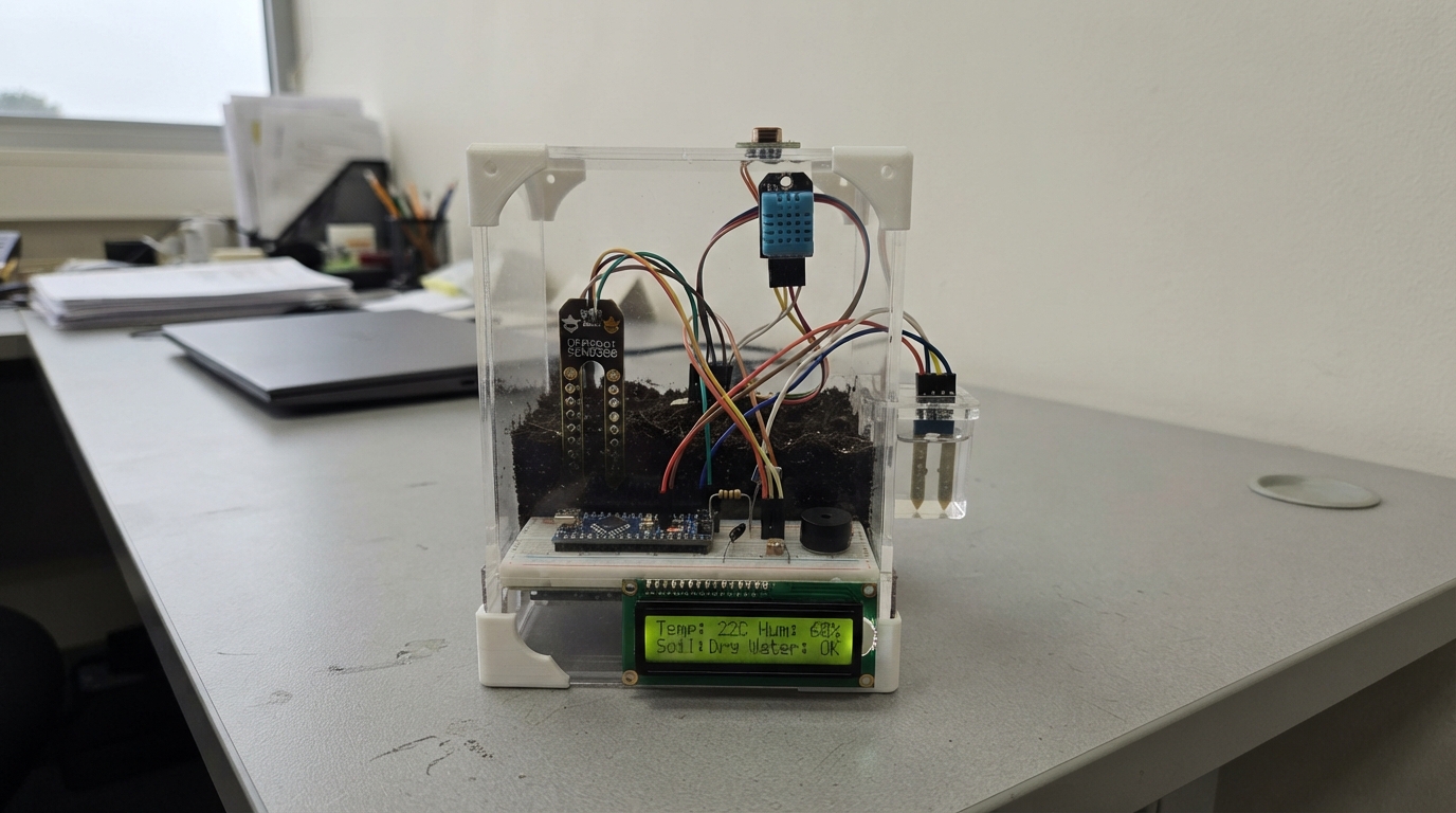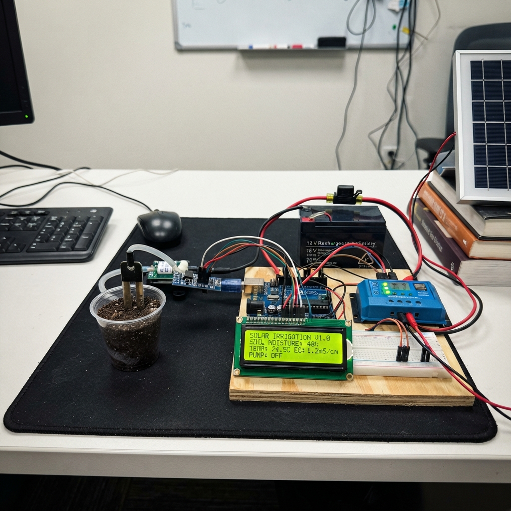
This solar-powered irrigation system automatically waters plants based on real-time soil conditions. The 7-in-1 soil sensor monitors moisture, temperature, pH, and nutrient levels (nitrogen, phosphorus, potassium), while the Arduino Uno controls a 12 V diaphragm pump to deliver water when soil moisture drops below a set threshold. The system runs entirely off a solar panel and rechargeable battery, making it ideal for remote garden beds, potted plants, or greenhouse applications.
This guide provides a complete wiring diagram, parts list, and step-by-step assembly instructions for mounting all components in a weatherproof enclosure. You'll also get the full Arduino firmware that reads the soil sensor via RS485 Modbus protocol, displays live readings on a 20x4 LCD screen, and manages pump cycles with safety features like flyback diode protection and fused power distribution.
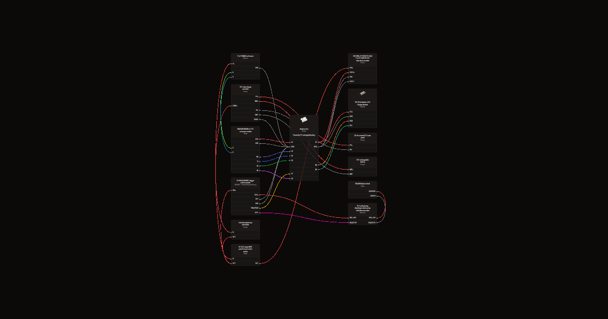
Wiring diagram
Gather all the parts
Assemble it in 9 steps
1. Mount the parts in a dry box
Mount the Arduino Uno, LCD, MAX485 converter, 5 V converter, fuse holder, pump switch, and master rocker switch inside a splash-proof box above the nutrient tank. Mount the external diaphragm pump beside or below the tank, not inside it. Keep the battery disconnected while building.
- Use cable glands so a pull on an outside wire cannot pull it from a terminal.
- Water reaching the Arduino or exposed 12 V terminals can cause a short circuit and damage the parts.
2. Connect the battery and solar panel
Cover the solar panel first. Connect battery_12v BAT+ to solar_charge_controller BAT+ (battery power), then battery_12v BAT- to BAT- (ground). Next connect solar_panel_20w PV+ to PV+ (solar power) and PV- to PV- (solar return). Use a solar charge controller that matches the exact battery type.
- Connecting the battery first lets most solar controllers recognize the system voltage correctly.
- Swapping battery positive and negative can permanently damage the solar controller.
3. Wire the fuse and built-in on/off switch
Connect solar_charge_controller LOAD+ to inline_fuse IN (protected 12 V power). Connect inline_fuse OUT to master_power_switch IN (fused power). From master_power_switch OUT, split the switched 12 V wire to buck_12v_to_5v VIN+ (power), pump_mosfet VIN+ (pump supply power), and soil_sensor_7in1 V+ (sensor power). Keep solar_charge_controller LOAD- connected to the shared ground (ground).
- Buy a simple two-terminal SPST rocker switch rated for at least 12 V DC and 5 A. The switch turns the device on and off, but does not stop solar charging.
- Switch the positive 12 V wire, not the negative wire. Fit the 5 A fuse only after checking every wire.
4. Connect the 5 V power converter
Connect buck_12v_to_5v VIN- and VOUT- to the shared ground (ground). Connect buck_12v_to_5v VOUT+ to the Uno 5V pin (power), and VOUT- to Uno GND (ground). Connect pump_mosfet GND and soil_sensor_7in1 GND to the same shared ground.
- Before connecting the Uno, use a multimeter to check that the HW-688 output is about 5 V.
- Never connect 12 V to the Uno 5V pin; it will destroy the Arduino. Do not connect the HW-688 5 V output to VIN or the barrel jack.
5. Connect the soil probe and MAX485
Connect soil_sensor_7in1 A to rs485_converter A (data) and soil_sensor_7in1 B to rs485_converter B (data). Connect rs485_converter VCC to Uno 5V (power), GND to Uno GND (ground), RO to Uno D2 (sensor data), DI to Uno D3 (sensor data), DE to Uno D4 (send control), and RE to Uno D6 (receive control).
- If the screen says the sensor is offline, turn power off and swap only the A and B wires.
- Do not pull on the soil probe cable while placing the probe in soil; that can break its sealed connection.
6. Connect the 20 by 4 display
Connect lcd_20x4 VCC to Uno 5V (power), GND to Uno GND (ground), SDA to Uno A4 (screen data), and SCL to Uno A5 (screen clock).
- If the backlight turns on but letters do not show, slowly adjust the small contrast screw on the LCD backpack.
- Make sure VCC and GND are not swapped, because swapped power can damage the display.
7. Wire the external pump and protection diode
Connect XY-MOS VIN+ to the switched fused 12 V supply and VIN- to the load supply ground. Connect GND to Uno GND (signal reference), and TRIG/PWM to Uno D5 (pump-control signal). There is no separate VCC-to-5V wire. Connect pump_12v_diaphragm RED +12V to pump_mosfet OUT+ (pump positive power), and BLACK 0V to OUT- (switched pump return). Put flyback_diode across the pump leads: the striped CATHODE end goes to RED +12V and the unstriped ANODE end goes to BLACK 0V.
- Keep the diode wires short and close to the pump terminals so it protects the pump switch. Read the printed terminal labels; do not infer polarity from position. Keep the pump disconnected and fuse removed until electronics and sensor tests pass.
- The striped diode end must connect to pump positive. Reversing it makes a short circuit when the pump turns on.
8. Connect the inlet and outlet hoses
Push one hose from the nutrient tank onto the pump_12v_diaphragm INLET port (liquid enters here); put a small strainer on its tank end and keep it below the liquid level. Push a second hose onto the OUTLET port and route it to the plant pot or drip ring (liquid leaves here). Secure both hoses with clamps so they cannot suck air or leak.
- Keep the inlet hose short and free of sharp bends; a self-priming pump works best with the pump close to the tank.
- Do not let the pump run with an empty tank for long, and keep any leak away from electrical terminals.
9. Fill and turn on the watering system
Fill the nutrient tank with premixed solution, place the soil probe in the root-zone soil, then install the fuse and uncover the solar panel. For the first pump test, aim the outlet hose into a measuring jug, check for leaks, then use master_power_switch to turn the device on.
- Measure the liquid delivered during one 10-second run so you can later adjust the watering time if plants need more or less water.
- Keep the pump electrically disconnected until the soil sensor reads correctly; the program intentionally keeps it off when the sensor reading is unavailable.
Review all connections
1. Connections between "solar_panel_20w" and "Arduino"
2. Connections between "battery_12v" and "Arduino"
3. Connections between "solar_charge_controller" and "Arduino"
4. Connections between "inline_fuse" and "Arduino"
5. Connections between "master_power_switch" and "Arduino"
6. Connections between "buck_12v_to_5v" and "Arduino"
7. Connections between "soil_sensor_7in1" and "Arduino"
8. Connections between "rs485_converter" and "Arduino"
9. Connections between "lcd_20x4" and "Arduino"
10. Connections between "pump_mosfet" and "Arduino"
11. Connections between "pump_12v_diaphragm" and "Arduino"
12. Connections between "flyback_diode" and "Arduino"
Deploy the firmware
#include <Wire.h>
#include <SoftwareSerial.h>
#include <LiquidCrystal_I2C.h>
#include <ModbusMaster.h>

constexpr uint8_t LCD_ADDRESS = 0x27;
constexpr uint8_t LCD_COLUMNS = 20;
constexpr uint8_t LCD_ROWS = 4;
constexpr uint8_t RS485_RX_PIN = 2;
constexpr uint8_t RS485_TX_PIN = 3;
constexpr uint8_t RS485_DE_PIN = 4;
constexpr uint8_t PUMP_PIN = 5;
constexpr uint8_t RS485_RE_PIN = 6;
constexpr uint8_t SOIL_SENSOR_ID = 1;

// Most 7-in-1 RS485 probes report moisture in tenths of a percent.
constexpr uint16_t WATER_THRESHOLD_TENTHS = 350;  // 35.0 %
constexpr unsigned long PUMP_RUN_MS = 10000UL;
constexpr unsigned long MIN_CYCLE_INTERVAL_MS = 60000UL;
constexpr unsigned long SENSOR_POLL_MS = 2000UL;
constexpr unsigned long NUTRIENT_SCREEN_MS = 5000UL;

LiquidCrystal_I2C lcd(LCD_ADDRESS, LCD_COLUMNS, LCD_ROWS);
SoftwareSerial rs485Serial(RS485_RX_PIN, RS485_TX_PIN);
ModbusMaster soil;

struct SoilReadings {
  uint16_t moisture;
  int16_t temperature;
  uint16_t ec;
  uint16_t ph;
  uint16_t nitrogen;
  uint16_t phosphorus;
  uint16_t potassium;
};

SoilReadings readings = {};
bool sensorAvailable = false;
bool pumpRunning = false;
unsigned long pumpStartedAt = 0;
unsigned long lastCycleAt = 0;
unsigned long lastPollAt = 0;
unsigned long lastNutrientScreenAt = 0;
uint8_t nutrientScreen = 0;
bool displayDirty = true;

void beforeTransmission() {
  // DE HIGH turns on the transmitter; RE HIGH turns off the receiver.
  digitalWrite(RS485_RE_PIN, HIGH);
  digitalWrite(RS485_DE_PIN, HIGH);
}

void afterTransmission() {
  // DE LOW stops transmitting; RE LOW turns the receiver back on.
  digitalWrite(RS485_DE_PIN, LOW);
  digitalWrite(RS485_RE_PIN, LOW);
}

bool readSoilSensor() {
  const uint8_t result = soil.readHoldingRegisters(0x0000, 7);
  if (result != soil.ku8MBSuccess) return false;

  readings.moisture = soil.getResponseBuffer(0);
  readings.temperature = static_cast<int16_t>(soil.getResponseBuffer(1));
  readings.ec = soil.getResponseBuffer(2);
  readings.ph = soil.getResponseBuffer(3);
  readings.nitrogen = soil.getResponseBuffer(4);
  readings.phosphorus = soil.getResponseBuffer(5);
  readings.potassium = soil.getResponseBuffer(6);
  return true;
}

void clearLine(uint8_t row) {
  lcd.setCursor(0, row);
  lcd.print(F("                    "));
}

void updateDisplay() {
  if (!displayDirty) return;
  displayDirty = false;

  if (!sensorAvailable) {
    clearLine(0); clearLine(1); clearLine(2); clearLine(3);
    lcd.setCursor(0, 0); lcd.print(F("SENSOR NOT FOUND"));
    lcd.setCursor(0, 1); lcd.print(F("Pump held OFF"));
    lcd.setCursor(0, 2); lcd.print(F("Check RS485 A/B"));
    lcd.setCursor(0, 3); lcd.print(F("and 12V sensor power"));
    return;
  }

  clearLine(0); clearLine(1); clearLine(2); clearLine(3);
  lcd.setCursor(0, 0);
  lcd.print(F("Moist:")); lcd.print(readings.moisture / 10); lcd.print(F("%"));
  lcd.setCursor(0, 1);
  lcd.print(F("Temp:")); lcd.print(readings.temperature / 10); lcd.print(F("C EC:")); lcd.print(readings.ec);
  lcd.setCursor(0, 2);
  lcd.print(F("pH:")); lcd.print(readings.ph / 10);
  if (nutrientScreen == 0) {
    lcd.print(F(" N:")); lcd.print(readings.nitrogen);
  } else if (nutrientScreen == 1) {
    lcd.print(F(" P:")); lcd.print(readings.phosphorus);
  } else {
    lcd.print(F(" K:")); lcd.print(readings.potassium);
  }
  lcd.setCursor(0, 3);
  if (pumpRunning) lcd.print(F("PUMPING NOW *"));
  else if (readings.moisture <= WATER_THRESHOLD_TENTHS) lcd.print(F("Low: waiting 1 min"));
  else lcd.print(F("Moisture STABLE :)"));
}

void setup() {
  pinMode(RS485_DE_PIN, OUTPUT);
  pinMode(RS485_RE_PIN, OUTPUT);
  digitalWrite(RS485_DE_PIN, LOW);
  digitalWrite(RS485_RE_PIN, LOW);
  pinMode(PUMP_PIN, OUTPUT);
  digitalWrite(PUMP_PIN, LOW);

  rs485Serial.begin(4800);
  soil.begin(SOIL_SENSOR_ID, rs485Serial);
  soil.preTransmission(beforeTransmission);
  soil.postTransmission(afterTransmission);

  lcd.init();
  lcd.backlight();

  // Opening screen: the 20-column LCD needs the long description on two lines.
  // "MONITORING DEVICE" stays together, as requested.
  lcd.clear();
  lcd.setCursor(7, 0);
  lcd.print(F("SOLIS"));
  lcd.setCursor(1, 1);
  lcd.print(F("SOLAR POWERED SOIL"));
  lcd.setCursor(1, 2);
  lcd.print(F("MONITORING DEVICE"));
  delay(3000);
  lcd.clear();
}

void loop() {
  const unsigned long now = millis();

  if (pumpRunning && now - pumpStartedAt >= PUMP_RUN_MS) {
    digitalWrite(PUMP_PIN, LOW);
    pumpRunning = false;
    lastCycleAt = now;
    displayDirty = true;
  }

  if (sensorAvailable && now - lastNutrientScreenAt >= NUTRIENT_SCREEN_MS) {
    lastNutrientScreenAt = now;
    nutrientScreen = (nutrientScreen + 1) % 3;
    displayDirty = true;
  }

  if (now - lastPollAt >= SENSOR_POLL_MS) {
    lastPollAt = now;
    sensorAvailable = readSoilSensor();
    displayDirty = true;
    if (sensorAvailable && !pumpRunning && readings.moisture <= WATER_THRESHOLD_TENTHS &&
        now - lastCycleAt >= MIN_CYCLE_INTERVAL_MS) {
      digitalWrite(PUMP_PIN, HIGH);
      pumpRunning = true;
      pumpStartedAt = now;
      displayDirty = true;
    }
  }

  updateDisplay();
  delay(10);
}
Remix this project
Make it yours in one click
Open a full copy of this project in your own Schematik workspace, diagram, code, parts, and assembly steps included. Swap the sensor, add features, or redesign the whole thing with AI. The author's original stays untouched.