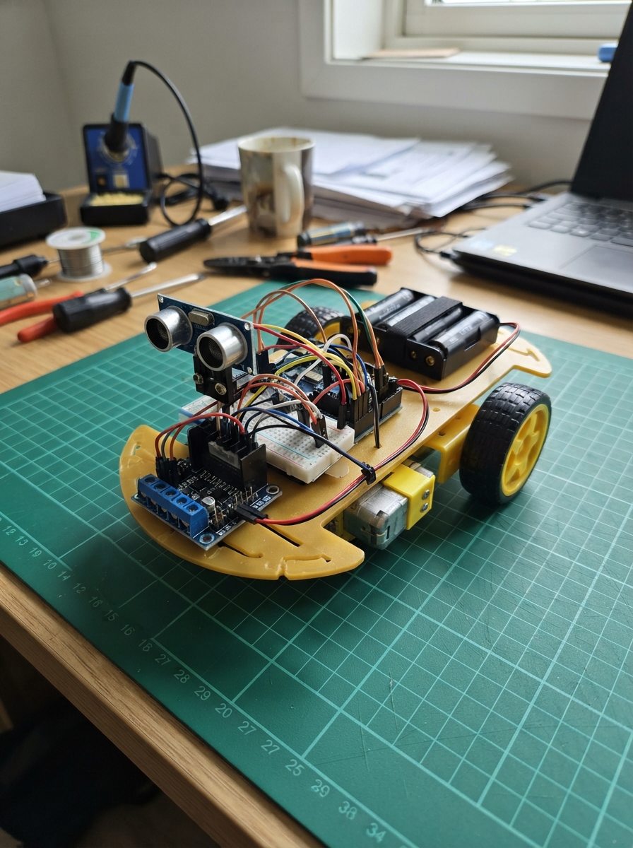
This autonomous obstacle-avoiding car uses an HC-SR04 ultrasonic sensor to detect barriers and navigate around them without human control. Built around an Arduino Uno, L298N motor driver, and a pair of N20 micro metal gear motors powered by four AA batteries, the car drives forward until an obstacle appears within 30 cm, then stops and scans left, center, and right to find the clearest path.
The guide provides a complete wiring diagram showing how to connect the motor driver to the Arduino and motors, a full parts list with ratings and specifications, and tested firmware that implements conservative obstacle detection and timed turning maneuvers. Assembly steps cover driver configuration, motor connection, sensor mounting, and safe testing procedures with the wheels raised before deployment on the floor.
Wiring diagram
Gather all the parts
Assemble it in 6 steps
1. Check the driver and motor ratings
Use the common L298N module with ENA, IN1-IN4, ENB and OUT1-OUT4 labels. This wiring is not for the DFRobot MDV board. The chosen example motors are small 6 V N20 gear motors; fit four matching wheels to a chassis.
- Check the combined stall current of each pair before connecting. Keep it below 2 A per channel and preferably below 1 A for thermal margin. Higher-current motors need a stronger driver; do not rely on PWM to make them safe.
2. Fit enable jumpers; remove regulator jumper
With all power disconnected, fit the ENA and ENB jumper caps to hold both channels enabled. No Uno wires go to ENA or ENB; the diagram's 5V enable connections represent these jumper caps. Remove only the separate 5V-EN regulator jumper. Connect IN1-IN4 to Uno D7-D10 for direction. D5 and D6 are unused. No enable pull-down resistors are needed.
- Do not confuse the ENA and ENB caps with the separate 5V-EN regulator cap. Leave the regulator cap removed when supplying logic from Uno 5V.
- Speed control is removed. Motors run at full available power; keep wheels raised during startup and reset tests.
3. Connect the four motors
Connect both left motors in parallel to OUT1 and OUT2. Connect both right motors in parallel to OUT3 and OUT4. The diagram assumes matching motor polarity; swap one motor's two wires if it fights the other wheel on its side.
4. Connect motor power and shared ground
Connect the four-AA pack positive to the driver terminal marked 12V (VS), and negative to driver GND and Uno GND. Connect Uno 5V to driver 5V for logic only. Power the Uno through its USB socket with a regulated 5 V USB source, separately from the motor pack. A portable USB supply must stay on at low current.
- Never power motors from the Uno 5V pin. Never connect the 6 V pack to Uno 5V. Disconnect motor power before handling wheels. L298N voltage loss reduces available speed and torque. Without the external capacitor, motor noise and supply dips may cause resets or erratic operation. Stop testing if that happens; extra power filtering may be needed.
5. Mount the distance sensor
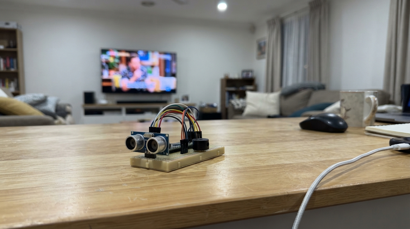
Fix the HC-SR04 facing forward at the very front of the car with its transducers unobstructed. VCC goes to Uno 5V, GND to GND, TRIG to D2 (measurement trigger), ECHO to D3 (distance pulse). No voltage divider is needed with this 5 V Uno.
6. Test with the wheels raised first
Secure the car with wheels off the ground. It starts after three seconds. Verify all wheels move forward together and a left turn spins the left wheels backward and right wheels forward. Disconnect power before swapping motor leads. Then test cautiously in a wide clear floor area at full motor power. Adjust QUARTER_TURN_MS until turns are about 90 degrees, and increase STOP_CM if braking needs more room. Turn timing must be recalibrated because speed control has been removed.
- A single forward sensor cannot protect the sides during turning or detect drop-offs. Keep the whole turning area clear. The 20 cm clearance is a target
- not a guarantee; soft or angled objects can be missed. Never test near stairs
- people or pets. No echo means stop
- which can also stop the car in a very open area.
Review all connections
1. Connections between "driver" and "Arduino"
2. Connections between "battery" and "Arduino"
3. Connections between "sonar" and "Arduino"
Deploy the firmware
#include <Arduino.h>
const uint8_t IN1=7, IN2=8, IN3=9, IN4=10, TRIG=2, ECHO=3;
// Enable jumpers fitted: full-power drive. Tune carefully on a clear floor. These are timed turns, not measured angles.
const unsigned long QUARTER_TURN_MS=430;
const int DRIVE_POWER=255, TURN_POWER=255;
const int STOP_CM=30; // 20 cm minimum target plus stopping allowance
const int CLEAR_CM=40;
bool preferLeft=true;
void stopMotors(){
  // Enable both bridges briefly with equal inputs for dynamic braking.
  digitalWrite(IN1,LOW); digitalWrite(IN2,LOW);
  digitalWrite(IN3,LOW); digitalWrite(IN4,LOW);
  delay(100);
}
void drive(int l,int r){
  // Reverse both channels to match the installed motor polarity.
  digitalWrite(IN1,l<0); digitalWrite(IN2,l>0);
  digitalWrite(IN3,r<0); digitalWrite(IN4,r>0);
}
int distanceCm(){
  static unsigned long last=0;
  while(millis()-last<65) delay(1);
  last=millis();
  digitalWrite(TRIG,LOW); delayMicroseconds(3);
  digitalWrite(TRIG,HIGH); delayMicroseconds(10); digitalWrite(TRIG,LOW);
  unsigned long us=pulseIn(ECHO,HIGH,25000UL);
  // Missing echoes are UNKNOWN, never interpreted as free space.
  return us ? int(us/58UL) : 0;
}
int scan(){
  int a=distanceCm(), b=distanceCm(), c=distanceCm();
  // Conservative: any missing echo keeps this direction blocked.
  if(!a || !b || !c) return 0;
  return min(a,min(b,c));
}
void quarterTurn(bool left){
  drive(left?-TURN_POWER:TURN_POWER,left?TURN_POWER:-TURN_POWER);
  delay(QUARTER_TURN_MS); stopMotors(); delay(150);
}
void chooseRoute(){
  stopMotors();
  int ranges[4]={0,0,0,0};
  // Scan a full circle while stationary between turns. 1=left, 2=back, 3=right.
  for(int i=1;i<=4;i++){
    quarterTurn(true); ranges[i%4]=scan();
  }
  int best=-1;
  int order[4]={preferLeft?1:3,preferLeft?3:1,2,0};
  for(int j=0;j<4;j++){
    int k=order[j];
    if(ranges[k]>=CLEAR_CM && (best<0 || ranges[k]>ranges[best])) best=k;
  }
  preferLeft=!preferLeft;
  if(best<0){Serial.println(F("No confirmed clear route; stopped")); delay(1000); return;}
  if(best==1) quarterTurn(true);
  if(best==2){quarterTurn(true); quarterTurn(true);}
  if(best==3) quarterTurn(false);
  // Loop rechecks the selected direction before moving forward.
}
void setup(){
  pinMode(IN1,OUTPUT); pinMode(IN2,OUTPUT); pinMode(IN3,OUTPUT); pinMode(IN4,OUTPUT);
  pinMode(TRIG,OUTPUT); pinMode(ECHO,INPUT);
  Serial.begin(9600); stopMotors(); delay(3000);
}
void loop(){
  int cm=distanceCm();
  Serial.print(F("Front cm: ")); Serial.println(cm);
  if(cm>STOP_CM) drive(DRIVE_POWER,DRIVE_POWER);
  else chooseRoute();
}
Remix this project
Make it yours in one click
Open a full copy of this project in your own Schematik workspace, diagram, code, parts, and assembly steps included. Swap the sensor, add features, or redesign the whole thing with AI. The author's original stays untouched.