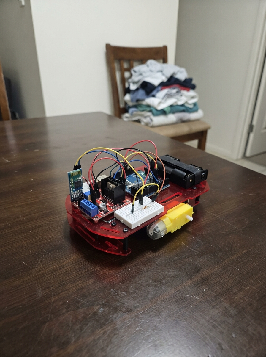
Build a four-wheel robot car controlled wirelessly via Bluetooth from a smartphone or tablet. This project combines an Arduino Uno microcontroller with an HC-05 Bluetooth module, L298N motor driver, and four geared motors to create a responsive mobile platform. The guide includes a complete wiring diagram, parts list, and step-by-step assembly instructions for mounting motors, connecting the motor driver, and safely integrating wireless control.
The included Arduino firmware handles Bluetooth communication, motor direction control, and speed adjustment through simple character commands (F for forward, B for backward, L for left turn, R for right turn, S for stop, and 0-9 for speed levels). Readers will learn how to wire dual motor control circuits, implement software serial communication, and build a safety timeout that stops the car if the connection drops.
Wiring diagram
Gather all the parts
Assemble it in 5 steps
1. Mount the four motors
Use a lightweight four-wheel chassis. Mount two BO motors on each side and fit matching wheels. Fasten the Uno, driver and battery holder securely.
2. Prepare the motor driver
Use the common red L298N module marked ENA, IN1, IN2, IN3, IN4, ENB. Remove all three jumpers: ENA, ENB and 5V-EN. Connect ENA to D5 and ENB to D6 for speed. Connect IN1 to D7, IN2 to D8, IN3 to D9 and IN4 to D10 for direction.
- Remove 5V-EN before connecting Uno 5V to driver 5V. Leaving it fitted can connect two power supplies together.
3. Connect the motor pairs
Connect both left motors in parallel to OUT1 and OUT2. Connect both right motors in parallel to OUT3 and OUT4. Each side shares one driver channel. With wheels lifted, check forward rotation; swap the two wires on any motor that spins backwards.
- Two stalled BO motors can exceed the L298N channel rating. Use only a lightweight car on a smooth floor. Stop immediately if wheels jam or the driver gets hot; do not use this for heavy loads.
4. Wire Bluetooth safely
HC-05 breakout Vcc goes to Uno 5V, GND to GND, and TX to D2 (received data). D3 goes through the 1 kohm resistor to HC-05 RX (sent data). Connect the 2 kohm resistor between RX and GND. This lowers the 5V signal to about 3.3V. Leave KEY and STATE unconnected.
- Use a HC-05 breakout with a voltage regulator, not the bare 3.3V radio board. Never connect D3 directly to HC-05 RX.
5. Connect separate motor and logic power
With the battery switch off, fit four AA alkaline cells. Holder positive goes to driver VS (often labelled +12V), negative to driver GND. Join driver GND to Uno GND. Connect Uno 5V to driver 5V for logic only. Supply Uno through its USB socket, using a computer for bench tests or a regulated USB power bank for driving.
- Never connect the 6V battery to Uno 5V. Motors must not draw power from Uno pins or USB. The L298N loses voltage, so this 6V setup is deliberately modest in speed.
Review all connections
1. Connections between "bt" and "Arduino"
2. Connections between "r1" and "Arduino"
3. Connections between "r2" and "Arduino"
4. Connections between "driver" and "Arduino"
5. Connections between "battery" and "Arduino"
Deploy the firmware
#include <Arduino.h>
#include <SoftwareSerial.h>
// SoftwareSerial is included in the Uno Arduino framework.
SoftwareSerial bluetooth(2, 3);
const uint8_t ENA=5, ENB=6, IN1=7, IN2=8, IN3=9, IN4=10;
uint8_t speedValue=160;
char motion='S';
unsigned long lastCommand=0;
void drive(char command) {
  // Disable outputs before changing direction.
  analogWrite(ENA,0); analogWrite(ENB,0);
  digitalWrite(IN1,LOW); digitalWrite(IN2,LOW);
  digitalWrite(IN3,LOW); digitalWrite(IN4,LOW);
  if(command=='S') return;
  delay(20);
  bool leftForward=command=='F'||command=='R';
  bool rightForward=command=='F'||command=='L';
  digitalWrite(IN1,leftForward); digitalWrite(IN2,!leftForward);
  digitalWrite(IN3,rightForward); digitalWrite(IN4,!rightForward);
  analogWrite(ENA,speedValue); analogWrite(ENB,speedValue);
}
void setup() {
  for(uint8_t p=5;p<=10;p++) { digitalWrite(p,LOW); pinMode(p,OUTPUT); }
  drive('S');
  bluetooth.begin(9600);
}
void loop() {
  if(bluetooth.available()) {
    char c=bluetooth.read();
    if(c>='a'&&c<='z') c-=32;
    if(c=='F'||c=='B'||c=='L'||c=='R'||c=='S') {
      lastCommand=millis();
      if(c!=motion) { motion=c; drive(motion); }
    } else if(c>='0'&&c<='9') {
      speedValue=(c-'0')*255/9;
      drive(motion);
    }
  }
  if(motion!='S' && millis()-lastCommand>600) { motion='S'; drive('S'); }
}
Remix this project
Make it yours in one click
Open a full copy of this project in your own Schematik workspace, diagram, code, parts, and assembly steps included. Swap the sensor, add features, or redesign the whole thing with AI. The author's original stays untouched.