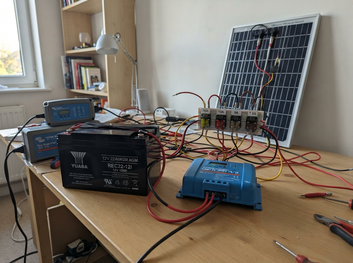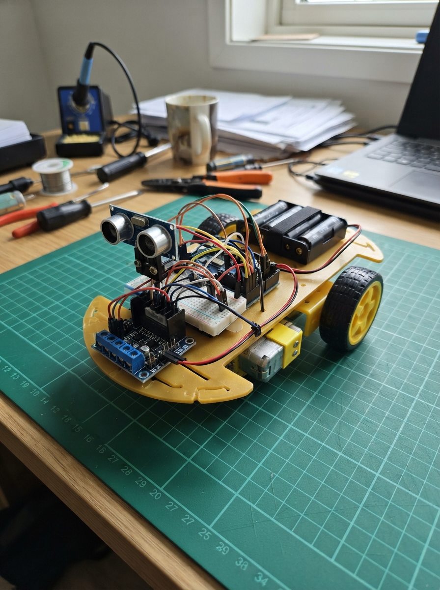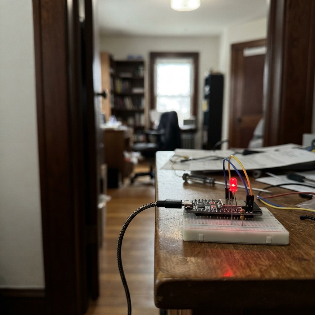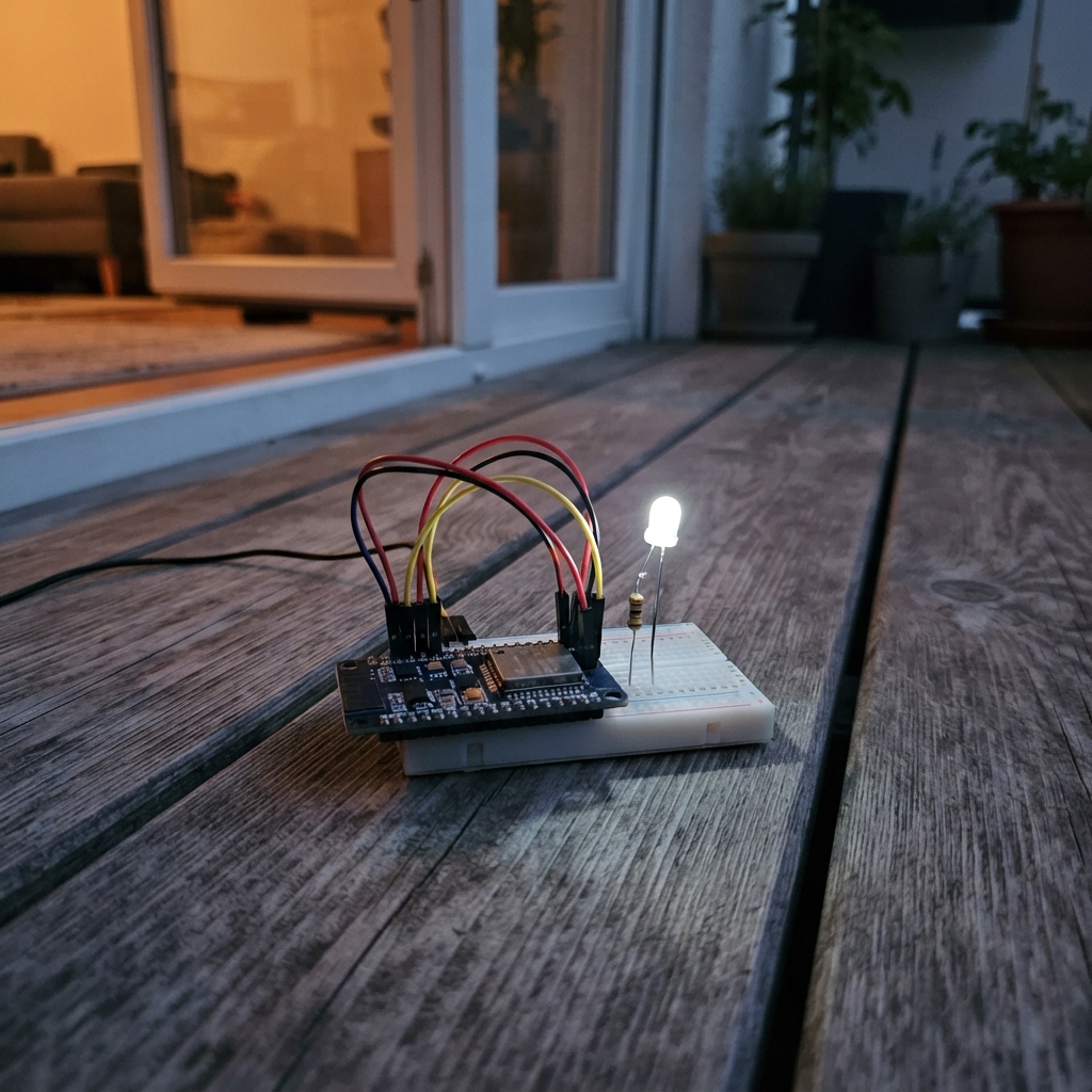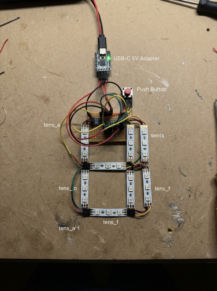
This project builds a two-digit score display using addressable RGB LED strips arranged in seven-segment numerals. Four push buttons increment the score by 10, 5, 2, or 1 points respectively, with debouncing logic to handle simultaneous presses and held buttons cleanly.
The guide includes a complete wiring diagram showing how to chain the WS2812B segments together, a full parts list, Arduino firmware with seven-segment font rendering, and step-by-step assembly instructions for cutting and soldering the LED strips into digit shapes.
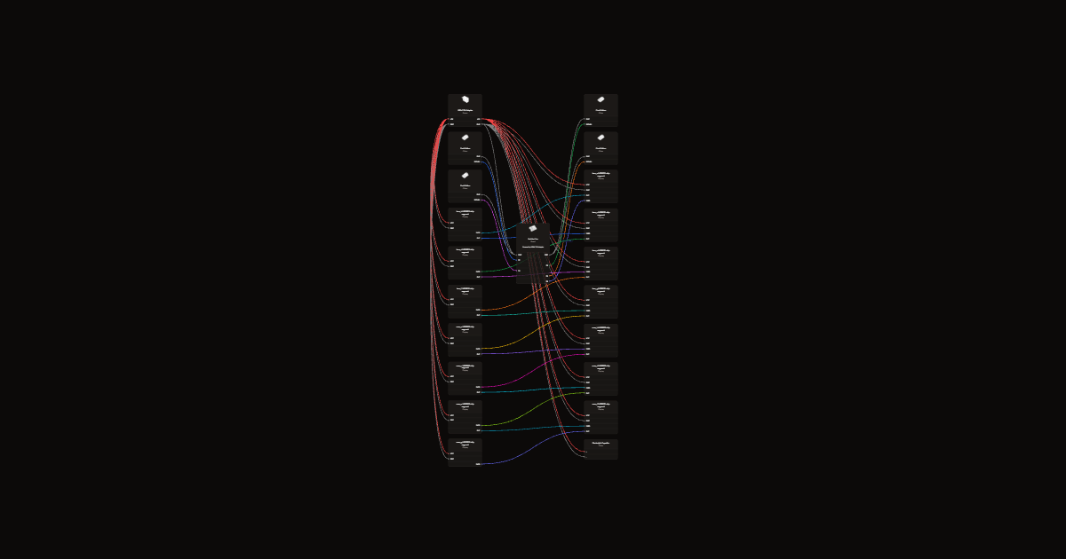
Wiring diagram
Gather all the parts
Assemble it in 7 steps
1. Buy the correct strip
Use 2 meters of 5 V WS2812B RGB strip at 60 LEDs per meter, individually cuttable after each LED. Do not use 12 V, RGBW, or grouped-pixel strip. Use a regulated isolated 5 V 4 A USB-C adapter with a matching prewired 5 V output cable rated for 4 A. USB powers Uno separately. The old 12 V supply is removed.
- Never connect the old 12 V adapter to these strips. It will destroy them.
2. Cut fourteen equal bars
Disconnect all power. Count FIVE LEDs for each bar, then cut through the middle of the marked copper cutting pads, never through an LED. At 60 LEDs/m each bar is approximately 83.3 mm (3.28 inches). Fourteen bars use 70 LEDs, about 1.17 meters. Buy 2 meters for spares. Label seven bars a through g for each digit.
3. Lay out two seven-inch numbers
Front view: a is top horizontal; b upper right; c lower right; d bottom horizontal; e lower left; f upper left; g middle horizontal. Mount all horizontal bars with data arrows pointing right; all vertical bars with arrows pointing down. Place the horizontal bar centerlines at y=0, 88.9, 177.8 mm. Vertical bars fit between these with small gaps; set their centerlines about 93.3 mm apart. This gives approximately 188 mm (7.4 inches) outside height for 10 mm wide strip. Leave 25 mm between digits. Attach to a nonconductive backing and leave space behind for jumper wires.
4. Solder the data chain
Tin each pad and stripped wire end with a little solder first. Briefly heat both together, then let cool without moving. Follow the arrows: Uno D8 through the 330 ohm resistor to DIN of left a. Then DOUT to DIN in this EXACT order: left a,b,c,d,e,f,g, then right a,b,c,d,e,f,g. Use insulated flexible 22 AWG jumpers; route them behind the panel. Do not bend strip around corners. Last right g DOUT stays unconnected. Keep the first data lead short; put the resistor near first DIN.
- Use printed pad labels, not pad positions or wire colors. Insulate every solder joint and secure wires so they cannot pull off pads.
5. Solder power in parallel
Run short 18 AWG +5 V and ground supply wires to each digit, then short 22 AWG branches to EVERY bar. Every +5V pad joins supply positive; every GND pad joins supply negative. Data is chained; power is parallel, NOT in series. Connect capacitor positive to supply +5 V and striped negative to GND beside the first bar. Connect supply GND to Uno GND, but NOT supply positive to Uno 5V or VIN.
- Reversed capacitor polarity can make it burst. Disconnect USB and external power before soldering. Never route strip current through Uno or a solderless breadboard. Do not open the wall adapter.
6. Keep four score switches
Connect normally-open contacts between D2 and GND for 10, D3 and GND for 5, D4 and GND for 2, D5 and GND for 1. Internal pull-ups mean no switch resistors.
7. Inspect and test
Check solder bridges, power polarity and arrows before applying power. Power LEDs before Uno USB; switch Uno off before LEDs. Numbers are red at limited brightness. A press displays its score for ten seconds, then blanks. Another press restarts the timer; holding does not retrigger. Add translucent diffusers and dark dividers if desired. This is an indoor display, not weatherproof.
- Do not change to full-brightness white with this supply: 70 older pixels can require 4.2 A.
Review all connections
1. Connections between "switch1" and "Arduino"
2. Connections between "switch2" and "Arduino"
3. Connections between "switch3" and "Arduino"
4. Connections between "switch4" and "Arduino"
5. Connections between "data_resistor" and "Arduino"
6. Connections between "supply" and "Arduino"
7. Connections between "tens_a" and "Arduino"
8. Connections between "tens_b" and "Arduino"
9. Connections between "tens_c" and "Arduino"
10. Connections between "tens_d" and "Arduino"
11. Connections between "tens_e" and "Arduino"
12. Connections between "tens_f" and "Arduino"
13. Connections between "tens_g" and "Arduino"
14. Connections between "ones_a" and "Arduino"
15. Connections between "ones_b" and "Arduino"
16. Connections between "ones_c" and "Arduino"
17. Connections between "ones_d" and "Arduino"
18. Connections between "ones_e" and "Arduino"
19. Connections between "ones_f" and "Arduino"
Deploy the firmware
#include <Arduino.h>
#include <FastLED.h>
const uint8_t pins[] = {2, 3, 4, 5};
const uint8_t scores[] = {10, 5, 2, 1};
bool rawState[4], stableState[4];
unsigned long changedAt[4] = {};
unsigned long scoreStarted = 0;
bool showingScore = false;

const uint8_t font[] = {0x3F,0x06,0x5B,0x4F,0x66,0x6D,0x7D,0x07,0x7F,0x6F};
CRGB leds[70];
void displayScore(int score) {
  for (uint8_t digit=0; digit<2; ++digit) {
    uint8_t mask = 0;
    if (score >= 0 && (digit == 1 || score >= 10))
      mask = font[digit == 0 ? score / 10 : score % 10];
    for (uint8_t seg=0; seg<7; ++seg)
      for (uint8_t pixel=0; pixel<5; ++pixel)
        leds[digit*35 + seg*5 + pixel] = (mask & (1 << seg)) ? CRGB(64,0,0) : CRGB(0,0,0);
  }
  FastLED.show(); // Only transmit when the displayed score changes.
}
void ready() { displayScore(-1); }

void setup() {
  for (uint8_t i = 0; i < 4; ++i) {
    pinMode(pins[i], INPUT_PULLUP);
    rawState[i] = stableState[i] = digitalRead(pins[i]);
  }
  FastLED.addLeds<WS2812B, 8, GRB>(leds, 70);
  ready();
}

void loop() {
  unsigned long now = millis();
  // Debounce each switch; a held switch produces only one score.
  // If simultaneous presses settle together, lower switch number wins.
  int8_t pressed = -1;
  for (uint8_t i = 0; i < 4; ++i) {
    bool reading = digitalRead(pins[i]);
    if (reading != rawState[i]) {
      rawState[i] = reading;
      changedAt[i] = now;
    }
    if (reading != stableState[i] && now - changedAt[i] >= 30UL) {
      stableState[i] = reading;
      if (reading == LOW && pressed < 0) pressed = i;
    }
  }
  if (pressed >= 0) {
    displayScore(scores[pressed]);
    scoreStarted = millis();
    showingScore = true;
  }
  if (showingScore && millis() - scoreStarted >= 10000UL) {
    showingScore = false;
    ready();
  }
}
Remix this project
Make it yours in one click
Open a full copy of this project in your own Schematik workspace, diagram, code, parts, and assembly steps included. Swap the sensor, add features, or redesign the whole thing with AI. The author's original stays untouched.