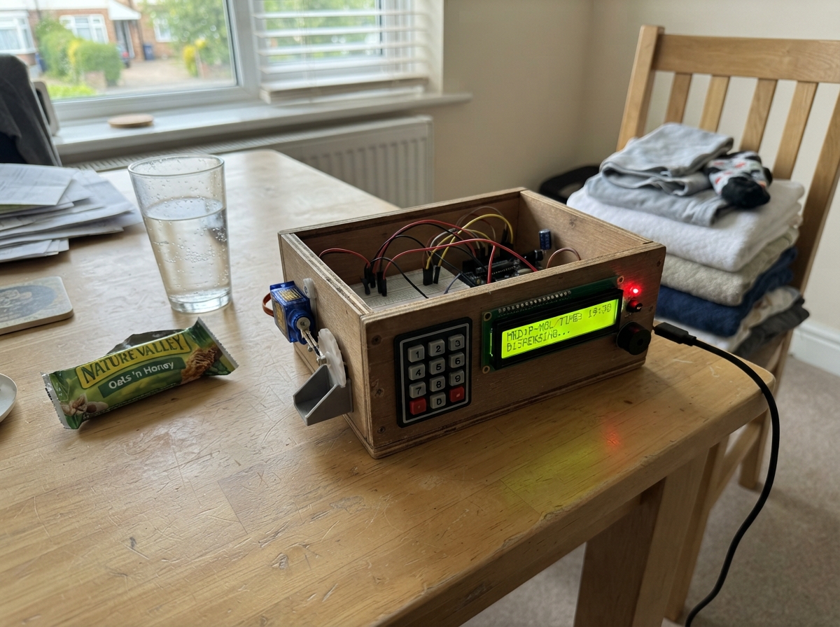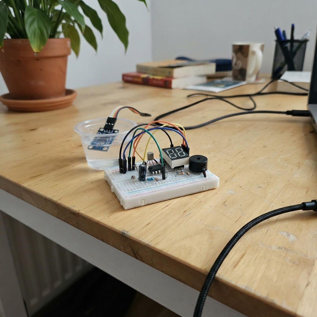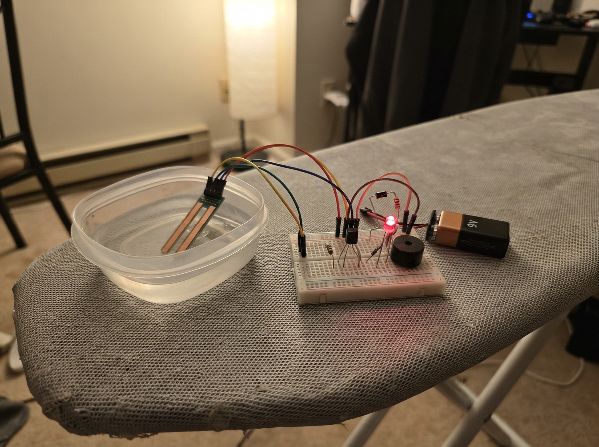
This flood early-warning alarm uses a water level sensor connected to an Arduino Uno to monitor rising water and alert users before dangerous levels are reached. The system displays three status states with LEDs (green for safe, yellow for warning, red for danger) and triggers an active buzzer when water reaches critical thresholds.
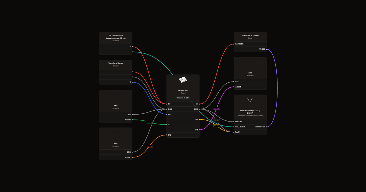
The guide provides a complete wiring diagram showing how to connect the water sensor to the analog input, wire the three status LEDs to digital outputs, and safely drive the buzzer using an NPN transistor with a flyback diode for protection. Assembly involves removing unused components, connecting the sensor directly, installing the status lights, and calibrating the warning thresholds by measuring actual water levels at your installation site. The included firmware handles sensor filtering and hysteresis to prevent false alarms.
Wiring diagram
Gather all the parts
Assemble it in 5 steps
1. Remove the unused display and boards
With USB disconnected, remove the seven-segment display and its seven resistors. Remove the LM358, ADS1115, MCP4725, their wiring, five signal-conditioning resistors and two capacitors. Keep the three LEDs and buzzer driver. Do not leave old wires connected to Uno pins.
2. Connect the water sensor directly
Connect sensor + to Uno 5V (power), - to GND (ground), and S to A0 (water reading). All ground connections can share one breadboard ground rail.
- Keep the header and electronics dry. Only the exposed sensing traces go in water. Disconnect power and rinse and dry the sensor after demonstrations to limit corrosion.
3. Connect the three status lights
Connect D10 through its own 220 ohm resistor to the green LED long leg (anode). Connect D11 through 220 ohms to the yellow long leg, and D12 through 220 ohms to the red long leg. Each short leg (cathode) goes to GND. Only one light is on at a time; green includes a dry sensor.
- Do not omit the LED resistors; excess current can damage LEDs or the Uno.
4. Keep the safe buzzer driver
Disconnect the base resistor from the removed DAC. Connect D9 through the existing 560 ohm resistor to transistor BASE. Keep the 10k resistor from BASE to GND. Connect EMITTER to GND and COLLECTOR to buzzer minus. Buzzer plus goes to 5V. Keep the diode across the buzzer with its banded cathode at 5V and anode at COLLECTOR. The buzzer pulses only in danger.
- Check the actual transistor pinout; 2N2222 and BC547 packages can have different leg orders. A reversed transistor can fail or leave the alarm silent.
- Use the specified 5V active buzzer rated at no more than 30mA. Do not connect it directly to D9.
5. Calibrate and test the warning levels
Secure the sensor vertically. Record filtered serial readings with water at your chosen warning and danger marks. Replace WARNING_COUNTS and DANGER_COUNTS in the firmware with these measurements, keeping danger higher than warning. The example settings 180 and 320 are not calibrated depths. Slowly raise and lower water to verify green, yellow, red and buzzer operation. Hysteresis of 15 counts prevents flickering near a threshold.
- This is a demonstration, not a life-safety flood alarm. Conductivity, contamination and corrosion change the readings; a disconnected sensor can look dry and show green.
Review all connections
1. Connections between "sensor" and "Arduino"
2. Connections between "r_green" and "Arduino"
3. Connections between "green" and "Arduino"
4. Connections between "r_yellow" and "Arduino"
5. Connections between "yellow" and "Arduino"
6. Connections between "r_red" and "Arduino"
7. Connections between "red" and "Arduino"
8. Connections between "r_base" and "Arduino"
9. Connections between "r_pulldown" and "Arduino"
10. Connections between "q1" and "Arduino"
11. Connections between "buzzer" and "Arduino"
12. Connections between "flyback" and "Arduino"
Deploy the firmware
#include <Arduino.h>
// Demonstration only: conductivity sensors cannot measure flood depth reliably.
constexpr uint8_t GREEN=10, YELLOW=11, RED=12, BUZZER=9;
// Uncalibrated examples in Uno ADC counts (0..1023), NOT millimetres.
// Measure readings at your actual warning/danger water marks and replace these.
constexpr int WARNING_COUNTS=180, DANGER_COUNTS=320, HYSTERESIS=15;
enum State { NORMAL, WARNING, DANGER };
State state=NORMAL;
float filtered=0;
uint32_t lastSample=0,lastPrint=0;
void setup(){
  digitalWrite(BUZZER,LOW); pinMode(BUZZER,OUTPUT);
  pinMode(GREEN,OUTPUT);pinMode(YELLOW,OUTPUT);pinMode(RED,OUTPUT);
  Serial.begin(115200);
  delay(100);
  filtered=analogRead(A0);
  Serial.println(F("DEMO ONLY: calibrate warning/danger counts. raw,filtered,state"));
}
void loop(){
  uint32_t now=millis();
  if(now-lastSample>=50){
    lastSample=now;
    int raw=analogRead(A0);
    filtered+=0.2f*(raw-filtered);
    if(filtered>=DANGER_COUNTS)state=DANGER;
    else if(state==DANGER){
      if(filtered<DANGER_COUNTS-HYSTERESIS)
        state=filtered>=WARNING_COUNTS-HYSTERESIS?WARNING:NORMAL;
    } else if(filtered>=WARNING_COUNTS)state=WARNING;
    else if(filtered<WARNING_COUNTS-HYSTERESIS)state=NORMAL;
    digitalWrite(GREEN,state==NORMAL);
    digitalWrite(YELLOW,state==WARNING);
    digitalWrite(RED,state==DANGER);
    if(now-lastPrint>=500){
      lastPrint=now;Serial.print(raw);Serial.print(',');
      Serial.print(filtered,1);Serial.print(',');
      Serial.println(state==NORMAL?F("LOW"):state==WARNING?F("WARNING"):F("DANGER"));
    }
  }
  digitalWrite(BUZZER,state==DANGER && (now%500)<250);
}
Remix this project
Make it yours in one click
Open a full copy of this project in your own Schematik workspace, diagram, code, parts, and assembly steps included. Swap the sensor, add features, or redesign the whole thing with AI. The author's original stays untouched.