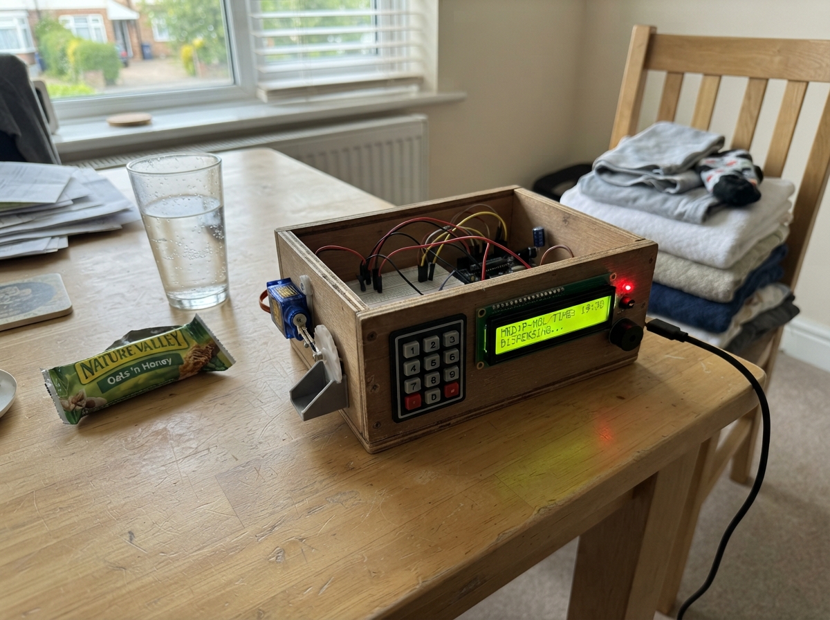
This smart medicine dispenser automates timed medication delivery using a servo-controlled rotating tray with four indexed positions. Built around an Arduino Uno, the system combines a 16x2 LCD display for status feedback, a 4x4 keypad for user input, and audio-visual alerts via a piezo buzzer and LED indicator to confirm each dispensing cycle.
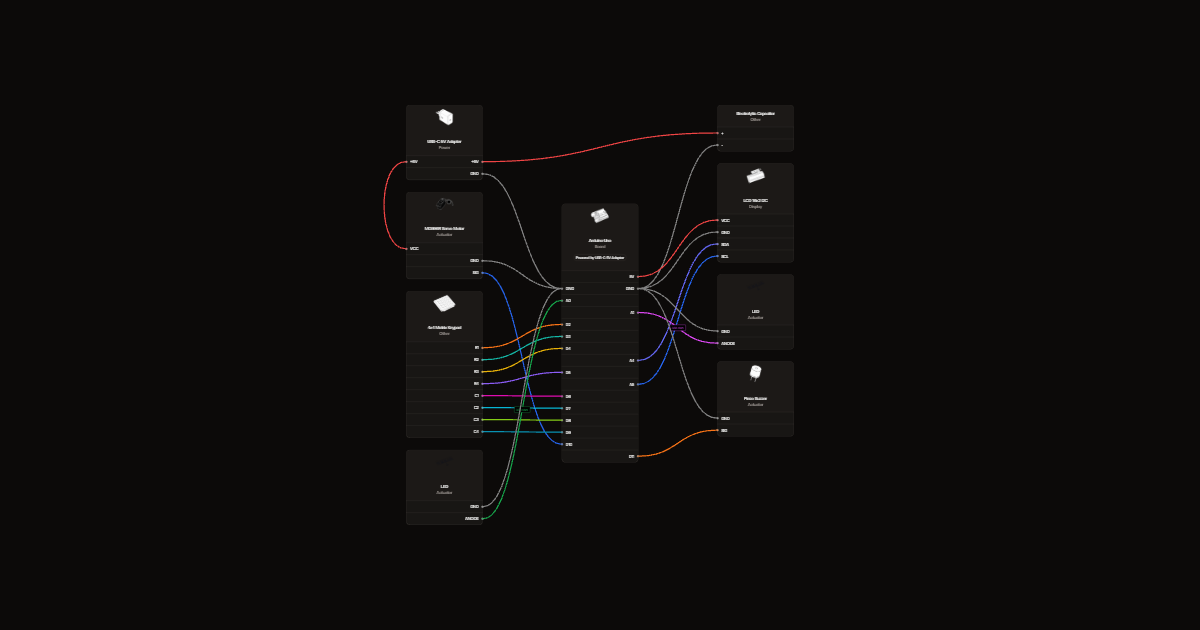
The guide provides a complete wiring diagram, parts list, and step-by-step assembly instructions for connecting the keypad, display, servo motor, and alert components. Included firmware handles interval scheduling, tray positioning, and user interaction through a state-based control system that requires calibration with an empty demonstration tray before operation.
Wiring diagram
Gather all the parts
Assemble it in 6 steps
1. Prepare a guarded demonstration tray
Use an MG996R bracket and a tray with four indexed dispensing positions over a half-turn, plus an empty home position. Firmware targets 0, 45, 90, 135 and 180 degrees. These are calibration starting points, not dimensions from the article. The article supplies no printable CAD files. Returning home sweeps backward through the positions; design a shutter or empty and inspect the tray before return so this cannot release extra dummy doses.
- Educational prototype only. Use dummy tablets only. No jam detection or confirmation of delivery or ingestion. Keep fingers away from the high-torque servo and cover moving parts.
2. Connect the keypad
Connect rows R1 through R4 to D2 through D5 and columns C1 through C4 to D6 through D9. Rows and columns scan which key is pressed. Identify row and column connections from your keypad pinout; ribbon order is not universal. No power wire is required.
3. Connect the screen
Connect VCC to Uno 5V and GND to GND. SDA to A4 carries data and SCL to A5 carries the clock signal. Firmware uses I2C address 0x27. Adjust the backpack contrast screw if text is faint.
4. Connect lights and sound
Connect A0 through the green LED's 330 ohm resistor to its anode; connect its cathode to GND. Connect A1 through the red LED's separate 330 ohm resistor to its anode and cathode to GND. Connect piezo SIG to D11 and GND to GND.
5. Power the servo separately
Use a regulated 5 V 3 A USB supply with an appropriate power cable or breakout. Connect supply positive to servo red VCC and capacitor positive. Connect supply ground, servo brown GND, capacitor negative and Uno GND together. Servo orange SIG goes to D10. Power Uno through its USB socket.
- Never connect the separate supply positive to Uno 5V. Do not use eight AA cells directly on the servo. Reversed electrolytic capacitor polarity can cause rupture. Do not wire mains electricity.
6. Check operation with an empty tray
Test with the servo horn removed first. Switch off power before attaching the horn. Check every position and the return path for collisions and unintended releases. Select 1 for seconds, 2 for minutes or 3 for hours; type a positive value and press hash to confirm. A starts four cycles, B pauses or resumes between movements, and D cancels and returns home. Star deletes a digit. Each interval is measured from the end of the previous movement. Pause does not interrupt a movement already started. Power loss cancels the session; inspect the tray before restarting.
- Use a short seconds interval and dummy tablets for testing. The maximum interval is 24 hours.
Review all connections
1. Connections between "gate" and "Arduino"
2. Connections between "supply" and "Arduino"
3. Connections between "bulk" and "Arduino"
4. Connections between "keypad" and "Arduino"
5. Connections between "display" and "Arduino"
6. Connections between "green" and "Arduino"
7. Connections between "rg" and "Arduino"
8. Connections between "red" and "Arduino"
9. Connections between "rr" and "Arduino"
10. Connections between "alarm" and "Arduino"
Deploy the firmware
#include <Arduino.h>
#include <Wire.h>
#include <Servo.h>
#include <Keypad.h>
#include <LiquidCrystal_I2C.h>
const byte SERVO_PIN=10, BUZZER_PIN=11, GREEN_PIN=A0, RED_PIN=A1;
// Calibration required with an empty tray. Four forward indexes within 180 degrees.
const byte POSITIONS[]={0,45,90,135,180};
char keys[4][4]={{'1','2','3','A'},{'4','5','6','B'},{'7','8','9','C'},{'*','0','#','D'}};
byte rows[]={2,3,4,5}, cols[]={6,7,8,9};
Keypad pad(makeKeymap(keys),rows,cols,4,4);
LiquidCrystal_I2C lcd(0x27,16,2);
Servo tray;
enum State {SET_UNIT,SET_VALUE,CONFIRM,RUNNING,PAUSED,MOVING,FINISHED,HOMING};
State state=SET_UNIT;
uint32_t value=0, multiplier=1, interval=0, remaining=0, tick=0, actionAt=0;
byte count=0; char unit='s';
char previous[2][17]={{0},{0}};
void line(byte row,const char* text) {
 char out[17]; memset(out,' ',16); out[16]=0;
 for(byte i=0;i<16 && text[i];i++) out[i]=text[i];
 if(strcmp(previous[row],out)) {lcd.setCursor(0,row);lcd.print(out);strcpy(previous[row],out);}
}
void show() {
 char a[32],b[32];
 switch(state) {
 case SET_UNIT: line(0,"Select time unit");line(1,"1:sec 2:min 3:hr");break;
 case SET_VALUE: snprintf(a,sizeof(a),"Interval: %lu %c",(unsigned long)value,unit);line(0,a);line(1,"#:OK *:erase");break;
 case CONFIRM: snprintf(a,sizeof(a),"Every %lu %c",(unsigned long)value,unit);line(0,a);line(1,"A:start D:cancel");break;
 case RUNNING: case PAUSED:
 snprintf(a,sizeof(a),"%s %lu s",state==PAUSED?"Paused":"Left",(unsigned long)((remaining+999)/1000));
 snprintf(b,sizeof(b),"%u/4 B:pause D:end",count);line(0,a);line(1,b);break;
 case MOVING: snprintf(a,sizeof(a),"Tray step %u/4",count);line(0,a);line(1,"D:cancel");break;
 case FINISHED:line(0,"Session complete");line(1,"Returning home");break;
 case HOMING:line(0,"Cancelled");line(1,"Returning home");break;
 }
}
void home(uint32_t now) {
 noTone(BUZZER_PIN);digitalWrite(GREEN_PIN,LOW);digitalWrite(RED_PIN,LOW);
 tray.write(POSITIONS[0]);state=HOMING;actionAt=now;
}
void setup() {
 pinMode(GREEN_PIN,OUTPUT);pinMode(RED_PIN,OUTPUT);pinMode(BUZZER_PIN,OUTPUT);
 Serial.begin(9600);Wire.begin();lcd.init();lcd.backlight();
 tray.write(POSITIONS[0]);tray.attach(SERVO_PIN,500,2500);
 Serial.println(F("DEMO ONLY: verify empty tray travel; no delivery or jam sensor."));show();
}
void loop() {
 uint32_t now=millis(),elapsed=now-tick;tick=now;
 if(state==RUNNING) remaining=elapsed>=remaining?0:remaining-elapsed;
 char k=pad.getKey();
 if(k=='D' && state!=HOMING) home(now);
 else if(state==SET_UNIT && k>='1' && k<='3') {
 multiplier=k=='1'?1:(k=='2'?60:3600);unit=k=='1'?'s':(k=='2'?'m':'h');value=0;state=SET_VALUE;
 } else if(state==SET_VALUE) {
 if(k>='0' && k<='9') {uint32_t next=value*10+(k-'0');if(next<=86400UL/multiplier)value=next;}
 if(k=='*')value/=10;
 if(k=='#' && value) {interval=value*multiplier*1000UL;state=CONFIRM;}
 } else if(state==CONFIRM && k=='A') {count=0;remaining=interval;state=RUNNING;}
 else if(state==RUNNING && k=='B')state=PAUSED;
 else if(state==PAUSED && k=='B')state=RUNNING;
 if(state==RUNNING && remaining==0) {
 ++count;tray.write(POSITIONS[count]);state=MOVING;actionAt=now;tone(BUZZER_PIN,2200,200);
 }
 if(state==MOVING) {
 digitalWrite(GREEN_PIN,((now-actionAt)/200)%2==0);
 if(now-actionAt>=1500) {
 digitalWrite(GREEN_PIN,LOW);
 if(count==4) {tray.write(POSITIONS[0]);state=FINISHED;actionAt=now;}
 else {remaining=interval;state=RUNNING;}
 }
 }
 if(state==FINISHED) {
 bool on=((now-actionAt)/250)%2==0;digitalWrite(RED_PIN,on);
 if(on)tone(BUZZER_PIN,3000);else noTone(BUZZER_PIN);
 if(now-actionAt>=3000) {noTone(BUZZER_PIN);digitalWrite(RED_PIN,LOW);state=SET_UNIT;}
 }
 if(state==HOMING && now-actionAt>=1500)state=SET_UNIT;
 show();
}
Remix this project
Make it yours in one click
Open a full copy of this project in your own Schematik workspace, diagram, code, parts, and assembly steps included. Swap the sensor, add features, or redesign the whole thing with AI. The author's original stays untouched.