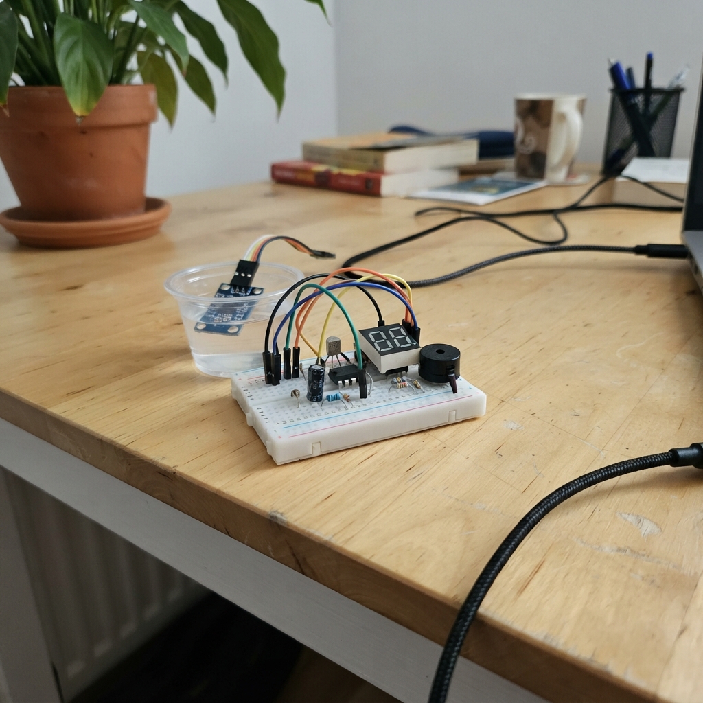
This flood early-warning alarm detects rising water levels using a capacitive sensor and alerts users with visual and audible warnings. The system conditions the sensor signal through an operational amplifier circuit, displays water depth on a seven-segment display, and triggers a buzzer and status LEDs when water reaches warning and danger thresholds.
Builders will receive a complete wiring diagram, parts list, calibration procedure, and Arduino firmware with moving-average filtering for stable readings. The guide covers constructing the analog signal conditioning stage, building the buzzer driver circuit with flyback protection, connecting the display and indicator LEDs, and calibrating the sensor across a known water depth range for accurate measurements.
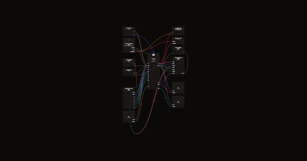
Wiring diagram
Gather all the parts
Assemble it in 6 steps
1. Prepare the dry electronics area
Keep the Uno and breadboard above the tray in a larger catch tub. Disconnect USB before wiring. Use the Uno 5V and GND rails; join every ground.
- Educational model only; never rely on this to protect people or property.
2. Build the sensor conditioner
Sensor + to 5V, - to GND. Signal passes through 10k to LM358 pin 3, with another 10k from pin 3 to GND. Pin 1 connects through 2.2k to pin 2; pin 2 connects through 10k to GND. Pin 1 then passes through 10k to A0. Connect sensor filter 10uF positive to A0, negative to GND. LM358 pin 8 to 5V, pin 4 to GND, 104 capacitor across pins 8 and 4.
- DIP pins count counterclockwise from the notch; pin 1 is upper left with notch at top.
- Sensor remains powered so the slow filter can settle; remove power and rinse/dry after demonstrations.
3. Build the DAC and buzzer driver
D9 through 1k to LM358 pin 5. Connect DAC 10uF positive to pin 5 and negative to GND. Join pins 7 and 6. Pin 7 through 560 ohms to transistor base; base through 10k to GND. Emitter to GND, collector to buzzer minus, buzzer plus to 5V. Diode banded cathode to 5V, anode to collector.
- Check the actual transistor manufacturer pinout; 2N2222 variants are not all ordered alike.
- Electrolytic negative stripe must face GND; reversed capacitors can fail.
4. Connect the seven segment display
5161AS front faces you, decimal point bottom right: bottom row left to right pins 1 to 5, top row left to right 10 to 6. Wire D2 through 220 ohms to pin 7 (a), D3 to pin 6 (b), D4 to pin 4 (c), D5 to pin 2 (d), D6 to pin 1 (e), D7 to pin 9 (f), D8 to pin 10 (g), each through its own 220 ohm resistor. Pins 3 and 8 to GND. Pin 5 decimal point unused.
5. Connect the status LEDs
D10 through 220 ohms to green anode, D11 through 220 ohms to yellow anode, D12 through 220 ohms to red anode. Each short cathode leg goes to GND.
6. Mark and calibrate the tray
Mount only the exposed sensor traces vertically in water, keeping its header dry. Mark depths 0 to 40mm in 5mm steps with a ruler. After filling each mark slowly, wait at least 2 seconds for settling. Record average ADC counts from serial output and replace the nine placeholder calibration values in firmware. Verify all values strictly increase.
- Calibration is essential; displayed depths and alarm thresholds are not valid with the placeholder table.
Review all connections
1. Connections between "sensor" and "Arduino"
2. Connections between "opamp" and "Arduino"
3. Connections between "r_div_top" and "Arduino"
4. Connections between "r_div_bottom" and "Arduino"
5. Connections between "r_feedback" and "Arduino"
6. Connections between "r_gain" and "Arduino"
7. Connections between "r_sensor_filter" and "Arduino"
8. Connections between "r_dac_filter" and "Arduino"
9. Connections between "r_base" and "Arduino"
10. Connections between "r_pulldown" and "Arduino"
11. Connections between "q1" and "Arduino"
12. Connections between "buzzer" and "Arduino"
13. Connections between "flyback" and "Arduino"
14. Connections between "c_sensor" and "Arduino"
15. Connections between "c_dac" and "Arduino"
16. Connections between "c_supply" and "Arduino"
17. Connections between "r_seg_a" and "Arduino"
18. Connections between "r_seg_b" and "Arduino"
19. Connections between "r_seg_c" and "Arduino"
20. Connections between "r_seg_d" and "Arduino"
21. Connections between "r_seg_e" and "Arduino"
22. Connections between "r_seg_f" and "Arduino"
23. Connections between "r_seg_g" and "Arduino"
24. Connections between "display" and "Arduino"
25. Connections between "r_green" and "Arduino"
26. Connections between "green" and "Arduino"
27. Connections between "r_yellow" and "Arduino"
28. Connections between "yellow" and "Arduino"
29. Connections between "r_red" and "Arduino"
30. Connections between "red" and "Arduino"
Deploy the firmware
#include <Arduino.h>
// Flood demonstration only, not a life-safety instrument.
constexpr uint8_t SENSOR=A0, DAC=9, GREEN=10, YELLOW=11, RED=12;
constexpr uint8_t segments[]={2,3,4,5,6,7,8}; // a b c d e f g
constexpr uint8_t digits[]={0x3f,0x06,0x5b,0x4f,0x66};
// PLACEHOLDERS: replace with measured A0 counts at 0,5,...40 mm.
// Old raw sensor endpoints 30..470 do NOT apply through this circuit.
constexpr uint16_t cal[]={18,52,85,119,153,186,220,253,287};
constexpr float depths[]={0,5,10,15,20,25,30,35,40};
enum State { NORMAL, WARNING, DANGER };
State state=NORMAL;
uint16_t samples[10]; uint32_t sum=0; uint8_t idx=0;
uint32_t lastSample=0,lastPrint=0; float mm=0; uint16_t raw=0;
float depth(float adc) {
  if(adc<=cal[0]) return 0;
  for(uint8_t i=1;i<9;i++) if(adc<=cal[i])
    return depths[i-1]+(adc-cal[i-1])*(depths[i]-depths[i-1])/(cal[i]-cal[i-1]);
  return 40;
}
void show(uint8_t level) {
  static uint8_t previous=255;
  if(previous==level)return;
  previous=level;
  for(uint8_t i=0;i<7;i++)digitalWrite(segments[i],(digits[level]>>i)&1);
}
void setup(){
  pinMode(DAC,OUTPUT);analogWrite(DAC,0);
  pinMode(GREEN,OUTPUT);pinMode(YELLOW,OUTPUT);pinMode(RED,OUTPUT);
  for(uint8_t p:segments)pinMode(p,OUTPUT);
  Serial.begin(115200);
  Serial.println(F("DEMO: UNCALIBRATED table. raw,average,mm,state,display"));
  // Allow both analog filters to settle; sensor stays powered during demo.
  delay(1000);
  raw=analogRead(SENSOR);
  for(uint8_t i=0;i<10;i++)samples[i]=raw;
  sum=10UL*raw;lastSample=millis();
}
void loop(){
  uint32_t now=millis();
  if(now-lastSample>=20){ // 50 Hz; no tone(), which can interfere with PWM
    lastSample=now;raw=analogRead(SENSOR);
    sum-=samples[idx];samples[idx]=raw;sum+=raw;idx=(idx+1)%10;
    mm=depth(sum/10.0f);
    // Entry at 10/25 mm, release at 8/23 mm.
    if(mm>=25)state=DANGER;
    else if(state==DANGER){if(mm<23)state=(mm>=8?WARNING:NORMAL);}
    else if(mm>=10)state=WARNING;
    else if(mm<8)state=NORMAL;
  }
  uint8_t level=mm<1?0:mm<10?1:mm<20?2:mm<25?3:4;
  show(level);
  bool pulse=(now%200)<100; // 5 Hz pulse envelope
  digitalWrite(GREEN,level>0 && state==NORMAL);
  digitalWrite(YELLOW,state==WARNING);
  digitalWrite(RED,state==DANGER && pulse);
  // 8-bit PWM DAC: 128/255 * 5V ~=2.51V. RC + LM358B -> NPN.
  // Only danger drives buzzer; other states command zero volts.
  analogWrite(DAC,state==DANGER && pulse?128:0);
  if(now-lastPrint>=500){
    lastPrint=now;Serial.print(raw);Serial.print(',');Serial.print(sum/10.0f,1);
    Serial.print(',');Serial.print(mm,1);Serial.print(',');Serial.print((int)state);
    Serial.print(',');Serial.println(level);
  }
}
Remix this project
Make it yours in one click
Open a full copy of this project in your own Schematik workspace, diagram, code, parts, and assembly steps included. Swap the sensor, add features, or redesign the whole thing with AI. The author's original stays untouched.