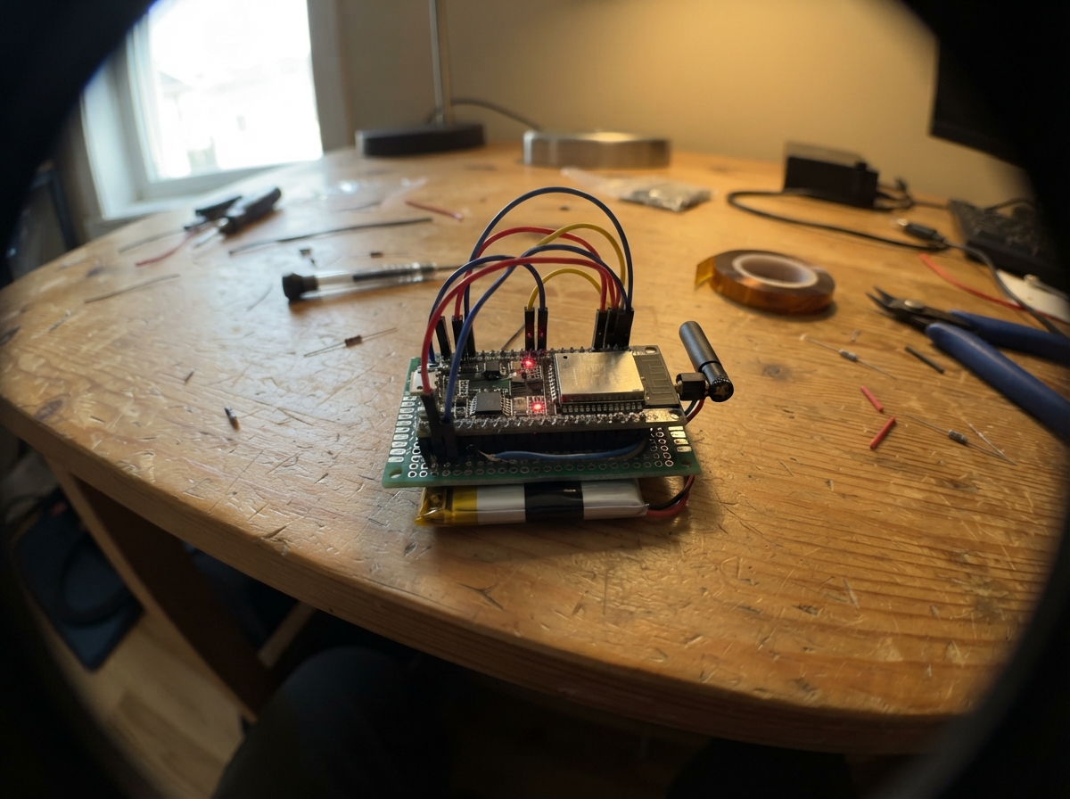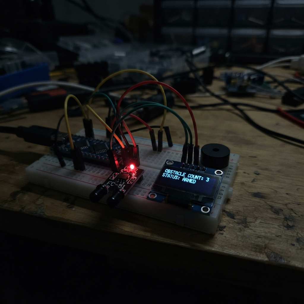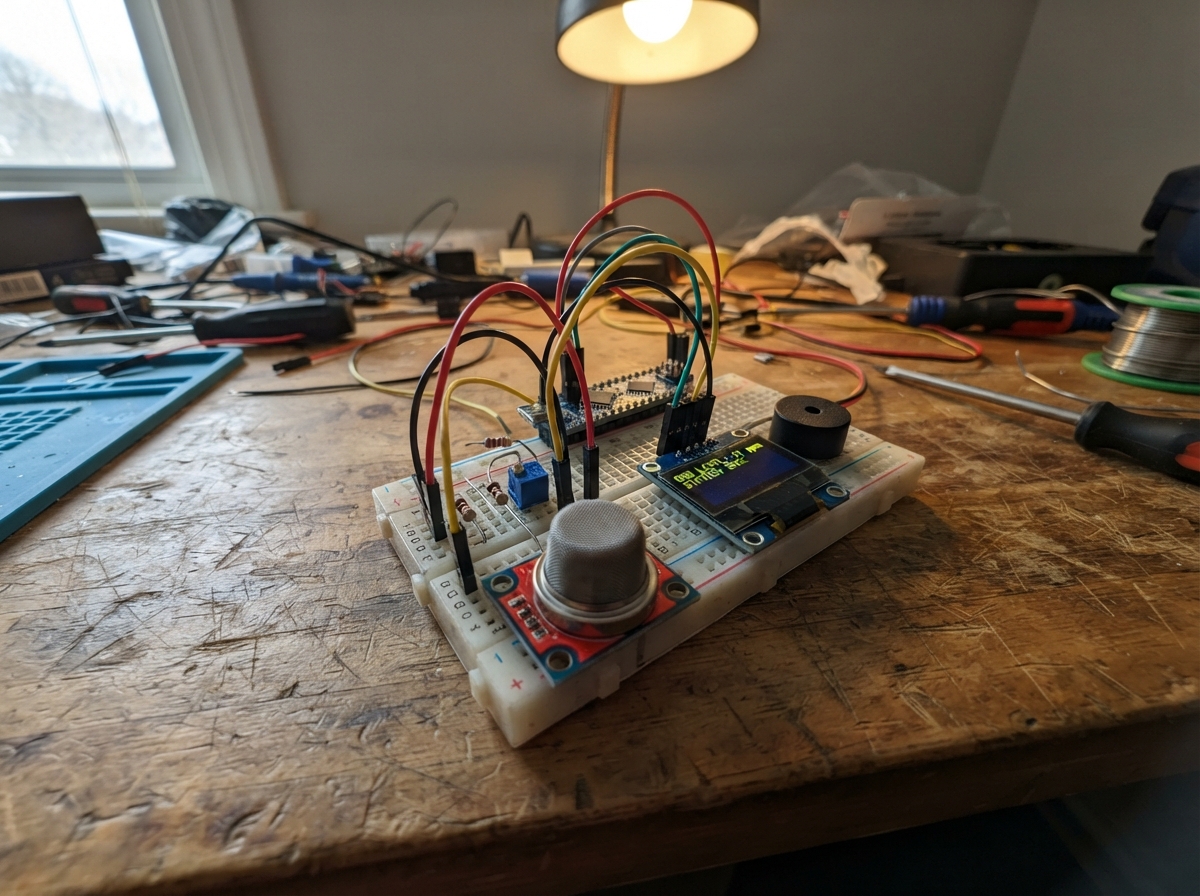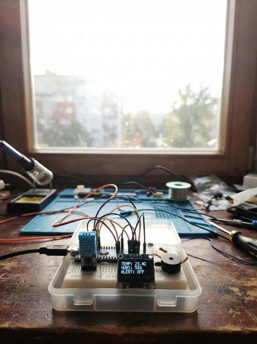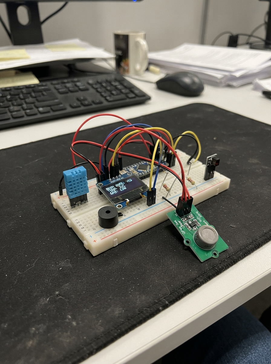
This project builds a multi-sensor safety monitor for indoor environments using an ESP32 microcontroller. It combines temperature and humidity monitoring via DHT11, infrared motion detection with the TCRT5000 module, and carbon monoxide detection using the MQ9 gas sensor. Real-time readings display on an SSD1306 OLED screen, while a piezo buzzer provides audio alerts when unsafe conditions are detected.
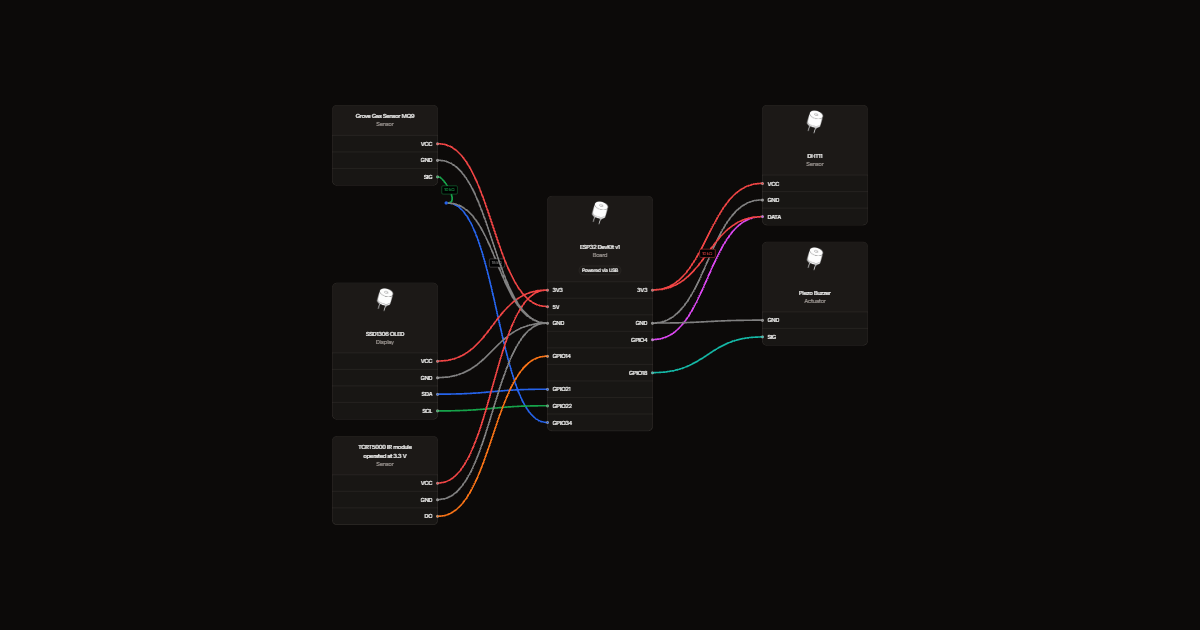
The guide includes a complete wiring diagram showing how to connect each sensor to the ESP32's GPIO pins, a full parts list with resistor values for the voltage divider protecting the gas sensor input, and the complete Arduino firmware that monitors all sensors and triggers alerts based on configurable thresholds. Assembly steps walk through display connection, sensor integration, and buzzer verification, treating the gas sensor calibration as an experimental parameter to adjust based on your environment.
Wiring diagram
Gather all the parts
Assemble it in 5 steps
1. Connect the screen
With USB unplugged, connect OLED VCC to 3V3 and GND to GND. Connect SDA to GPIO21 (data) and SCL to GPIO22 (clock).
- Check the printed pin labels; swapped power can damage the screen.
2. Connect temperature and infrared sensors
Connect both sensors to 3V3 and GND. DHT DATA goes to GPIO4; connect the 10 kΩ pull-up between DATA and 3V3. IR DO goes to GPIO14; leave AO disconnected. Adjust the IR trim-pot while testing the nearby target.
- The reflective IR sensor senses nearby surfaces roughly 1–25 mm away. It is not a room motion detector; verify its LOW detection state with your target.
3. Protect the gas input
Connect Grove MQ9 VCC to the USB-powered 5V rail and GND to GND. SIG goes through the 10 kΩ resistor to GPIO34. Connect the 15 kΩ resistor from GPIO34 to GND. Leave NC disconnected.
- Never connect SIG directly to GPIO34; the 5 V signal can damage the ESP32. The divider reduces 5 V to 3 V.
4. Connect the sounder and inspect
Connect piezo SIG to GPIO18 (sound) and its other lead to GND. Check every wire before connecting USB power.
5. Treat this as an experiment
Allow the gas sensor its manufacturer-recommended initial preheat of 24 hours in clean air. Observe the raw gas readings and tune the experimental 1800 threshold after the divider. Keep the heated sensor clear of flammable materials.
- This is not a certified gas or carbon monoxide alarm. Do not rely on it for life safety or test it by releasing fuel gas. Use certified alarms for protection.
Review all connections
1. Connections between "oled" and "ESP32"
2. Connections between "dht" and "ESP32"
3. Connections between "dhtPullup" and "ESP32"
4. Connections between "ir" and "ESP32"
5. Connections between "buzzer" and "ESP32"
6. Connections between "gas" and "ESP32"
7. Connections between "gasBottom" and "ESP32"
Deploy the firmware
// Project 4: Combined Smart Room Safety Monitor
#include <Arduino.h>
#include <Wire.h>
#include <Adafruit_GFX.h>
#include <Adafruit_SSD1306.h>
#include <DHT.h>
#define OLED_ADDR 0x3C
#define DHT_PIN 4
#define MQ9_PIN 34
#define IR_PIN 14
#define BUZZER_PIN 18
const float TEMP_MAX = 32.0, TEMP_MIN = 15.0;
const int GAS_LIMIT = 1800; // Experimental threshold AFTER voltage divider; calibrate.
Adafruit_SSD1306 display(128, 64, &Wire, -1);
DHT dht(DHT_PIN, DHT11);
unsigned long lastDht = 0;
float tempC = NAN, hum = NAN;
bool dhtValid = false;
String previousFrame;
void setup() {
  Serial.begin(115200);
  pinMode(IR_PIN, INPUT);
  pinMode(BUZZER_PIN, OUTPUT);
  analogReadResolution(12);
  Wire.begin(21, 22);
  dht.begin();
  if (!display.begin(SSD1306_SWITCHCAPVCC, OLED_ADDR)) {
    Serial.println("OLED initialization failed");
    while (true) delay(1000);
  }
  display.setTextColor(SSD1306_WHITE);
  display.setTextWrap(false);
}
void loop() {
  if (millis() - lastDht >= 2000) {
    float t = dht.readTemperature(), h = dht.readHumidity();
    dhtValid = !isnan(t) && !isnan(h);
    if (dhtValid) { tempC = t; hum = h; }
    lastDht = millis();
  }
  int gas = analogRead(MQ9_PIN);
  bool ir = (digitalRead(IR_PIN) == LOW);
  bool gasAlert = (gas >= GAS_LIMIT);
  bool tempAlert = dhtValid && (tempC > TEMP_MAX || tempC < TEMP_MIN);
  String banner = "READINGS NORMAL";
  if (gasAlert) banner = "!! GAS LEAK ALERT !!";
  else if (tempAlert) banner = "! TEMP OUT OF RANGE !";
  else if (!dhtValid) banner = "CHECK TEMP SENSOR";
  else if (ir) banner = "IR ZONE DETECTED";
  char readings[48], gasLine[40], irLine[32];
  if (dhtValid) snprintf(readings, sizeof(readings), "Temp: %.1fC Hum: %.0f%%", tempC, hum);
  else snprintf(readings, sizeof(readings), "Temp/Hum: unavailable");
  snprintf(gasLine, sizeof(gasLine), "Gas ADC: %4d (%s)", gas, gasAlert ? "HIGH" : "OK");
  snprintf(irLine, sizeof(irLine), "IR Zone: %s", ir ? "DETECTED" : "CLEAR");
  String frame = String(readings) + gasLine + irLine + banner;
  if (frame != previousFrame) {
    display.clearDisplay();
    display.setTextSize(1);
    display.setCursor(0, 0); display.println("SMART SAFETY MONITOR");
    display.drawLine(0, 10, 127, 10, SSD1306_WHITE);
    display.setCursor(0, 15); display.print(readings);
    display.setCursor(0, 28); display.print(gasLine);
    display.setCursor(0, 41); display.print(irLine);
    display.drawLine(0, 51, 127, 51, SSD1306_WHITE);
    display.setCursor(0, 55); display.print(banner);
    display.display();
    previousFrame = frame;
  }
  if (gasAlert) {
    tone(BUZZER_PIN, 2500, 120); delay(150);
    tone(BUZZER_PIN, 1800, 120); delay(150); noTone(BUZZER_PIN);
  } else if (tempAlert) {
    tone(BUZZER_PIN, 2000, 180); delay(250); noTone(BUZZER_PIN);
  } else if (ir) {
    tone(BUZZER_PIN, 1400, 70); delay(150); noTone(BUZZER_PIN);
  } else {
    noTone(BUZZER_PIN); delay(200);
  }
}
Remix this project
Make it yours in one click
Open a full copy of this project in your own Schematik workspace, diagram, code, parts, and assembly steps included. Swap the sensor, add features, or redesign the whole thing with AI. The author's original stays untouched.