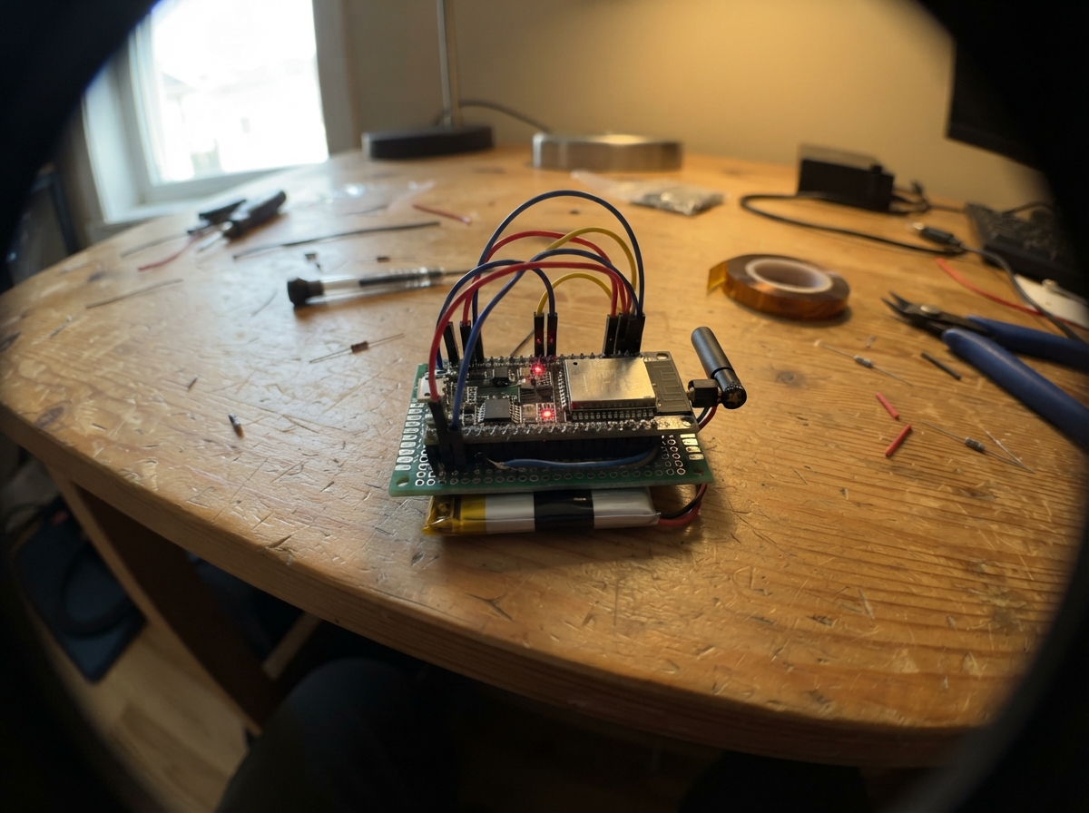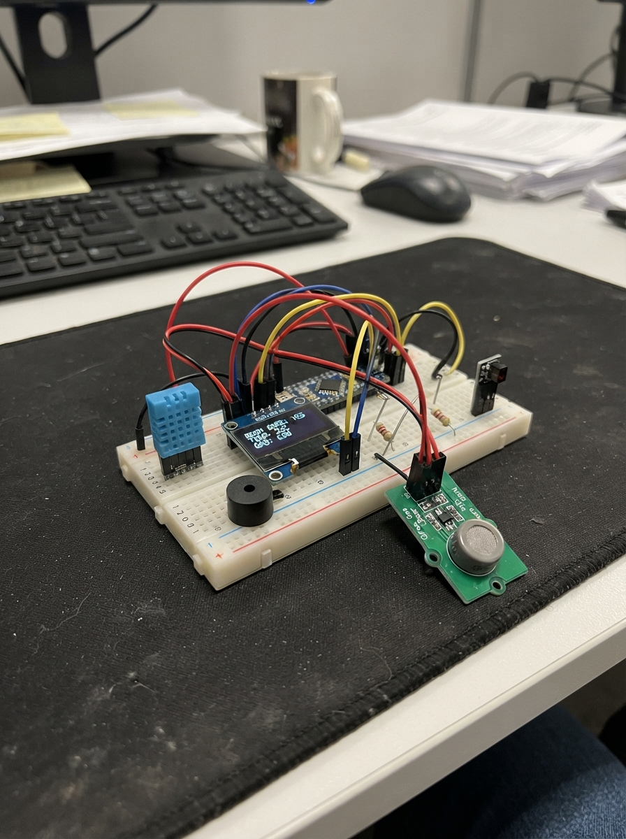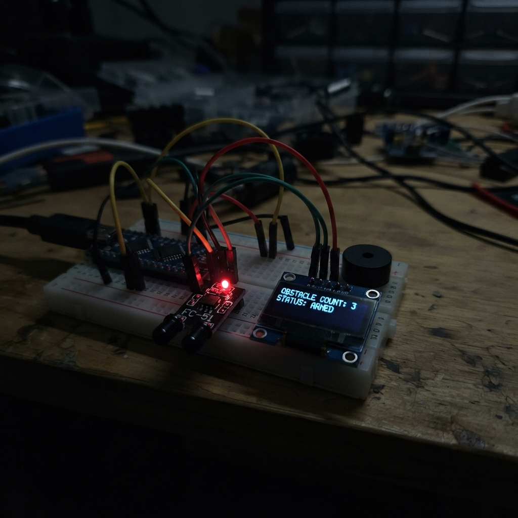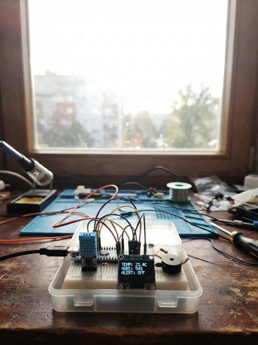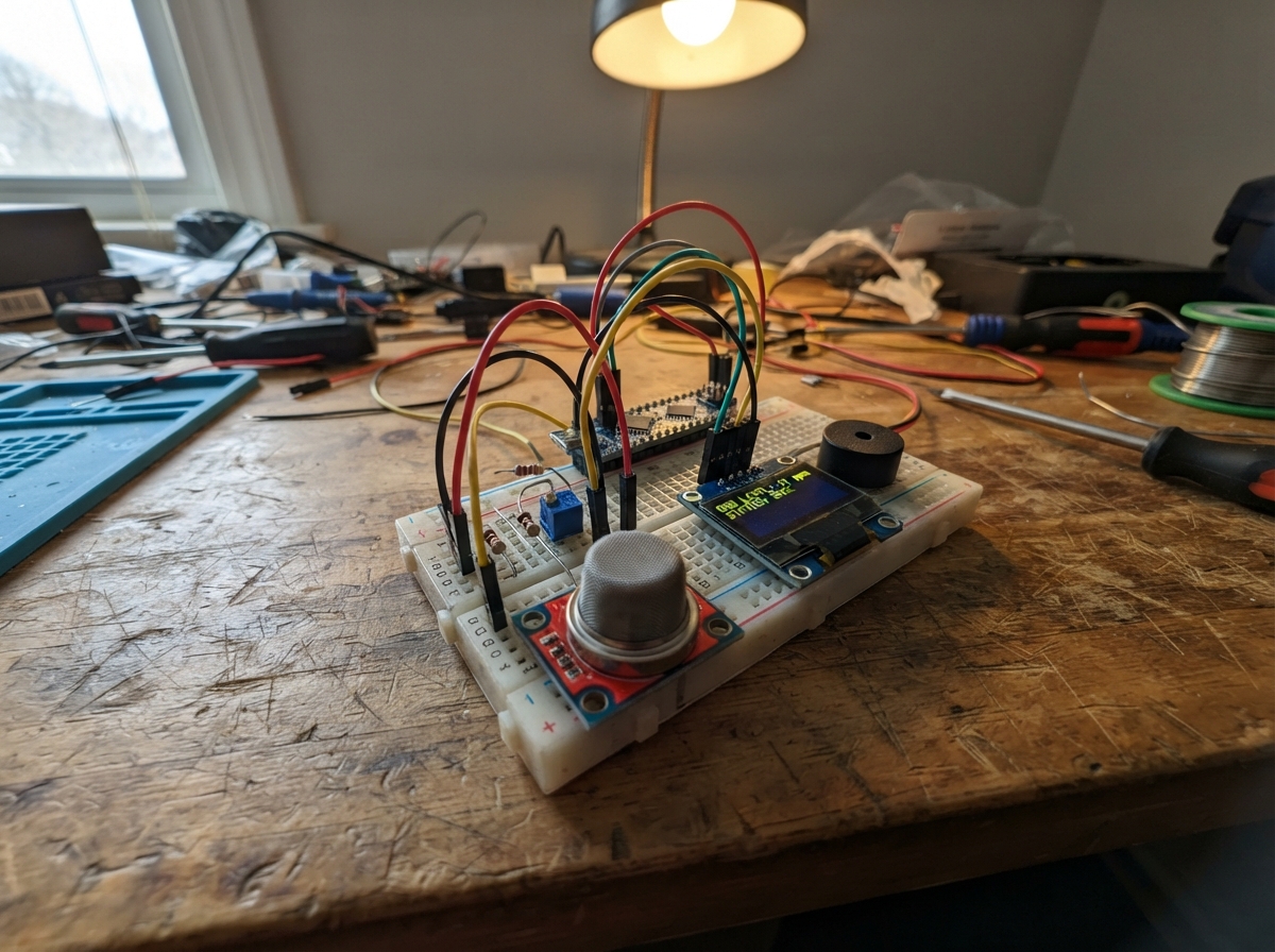
This project builds a gas leak alarm using an ESP32 microcontroller and an MQ-9 gas sensor to detect carbon monoxide and combustible gases. The system displays real-time sensor readings on an SSD1306 OLED screen and triggers a piezo buzzer when gas levels exceed a configurable threshold, providing visual and audible alerts for hazardous conditions.
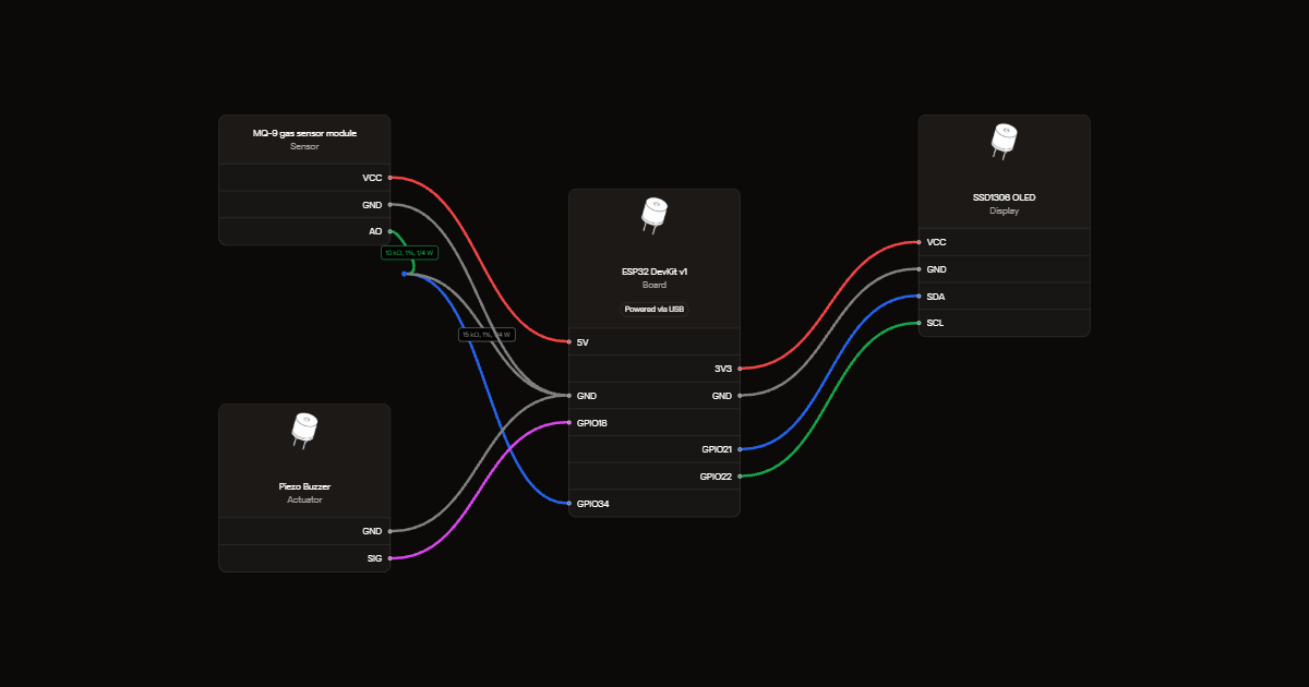
The guide includes a complete wiring diagram showing how to connect the MQ-9 sensor module, OLED display, and piezo buzzer to the ESP32 with proper voltage conditioning. Readers will receive a detailed parts list, step-by-step assembly instructions, and ready-to-upload firmware that handles sensor initialization, threshold detection, and display output. The project is designed as a learning platform for gas sensing and alarm systems—proper calibration and safety testing are essential before any real-world deployment.
Wiring diagram
Gather all the parts
Assemble it in 5 steps
1. Connect the gas module with power disconnected
Use a four-pin MQ-9 module, not a bare sensor. Connect VCC to the ESP32 USB-fed 5V pin and GND to GND. Leave DO disconnected. Use a reliable USB supply rated at least 1 A.
- The heater gets hot. Keep it away from flammable materials. This is an educational monitor, never a replacement for a certified gas or CO alarm.
2. Protect the sensor input
Connect MQ-9 AO to one end of the 10 kΩ resistor. Connect its other end to GPIO34 and one end of the 15 kΩ resistor. Connect the remaining 15 kΩ end to GND. These resistors reduce a 5 V signal to about 3 V.
- Never connect AO directly to GPIO34; a 5 V signal can damage the ESP32.
3. Connect the screen
Connect OLED VCC to 3V3, GND to GND, SDA to GPIO21 (data), and SCL to GPIO22 (clock). Follow the printed pin labels, not header position.
4. Connect the passive piezo
Connect one piezo lead to GPIO18 (tone signal) and the other to GND. Use the specified passive piezo, not a magnetic buzzer or higher-current sounder.
5. Check and condition the sensor
Check all connections before applying USB power. The 20-second countdown is only startup, not calibration. Allow initial conditioning of at least 48 hours in ventilated clean air, supervised and away from flammable materials. Record the stable clean-air ADC baseline before choosing a threshold.
- Fixed 5 V heater modules do not implement MQ-9 low/high heater cycling required for selective CO measurement. Readings are raw ADC values, not ppm or proof of safe air. Do not test using released gas, exhaust, or a flame.
Review all connections
1. Connections between "mq9" and "ESP32"
2. Connections between "rtop" and "ESP32"
3. Connections between "rbottom" and "ESP32"
4. Connections between "oled" and "ESP32"
5. Connections between "buzzer1" and "ESP32"
Deploy the firmware
#include <Arduino.h>
#include <Wire.h>
#include <Adafruit_GFX.h>
#include <Adafruit_SSD1306.h>
#define OLED_ADDR 0x3C
#define MQ9_PIN 34
#define BUZZER_PIN 18
const int GAS_LIMIT = 1800; // Experimental threshold; recalibrate with divider fitted.
Adafruit_SSD1306 display(128, 64, &Wire, -1);
void setup() {
  Serial.begin(115200);
  pinMode(BUZZER_PIN, OUTPUT);
  digitalWrite(BUZZER_PIN, LOW);
  analogReadResolution(12);
  analogSetPinAttenuation(MQ9_PIN, ADC_11db);
  Wire.begin(21, 22);
  if (!display.begin(SSD1306_SWITCHCAPVCC, OLED_ADDR)) {
    Serial.println("OLED initialization failed; check wiring.");
    while (true) { delay(1000); }
  }
  display.setTextColor(SSD1306_WHITE);
  // Startup countdown only, NOT sufficient sensor conditioning.
  for (int i = 20; i > 0; i--) {
    display.clearDisplay();
    display.setTextSize(1); display.setCursor(10, 24);
    display.printf("MQ-9 Starting: %ds", i);
    display.setCursor(0, 48); display.print("NOT A SAFETY ALARM");
    display.display(); delay(1000);
  }
}
void loop() {
  int gas = analogRead(MQ9_PIN);
  int bar = map(constrain(gas, 0, 4095), 0, 4095, 0, 120);
  bool danger = (gas >= GAS_LIMIT);
  static int lastGas = -1;
  if (gas != lastGas) {
    lastGas = gas;
    display.clearDisplay();
    display.setTextSize(1); display.setCursor(0, 0);
    display.println("MQ-9 GAS DEMO");
    display.drawLine(0, 10, 127, 10, SSD1306_WHITE);
    display.setTextSize(2); display.setCursor(0, 16);
    display.printf("ADC:%d", gas);
    display.drawRect(0, 38, 124, 10, SSD1306_WHITE);
    display.fillRect(2, 40, bar, 6, SSD1306_WHITE);
    display.setTextSize(1); display.setCursor(0, 54);
    display.print(danger ? "ALERT: ABOVE LIMIT" : "STATUS: BELOW LIMIT");
    display.display();
  }
  Serial.printf("ADC:%d Above limit:%d\n", gas, danger);
  if (danger) {
    tone(BUZZER_PIN, 2400, 150); delay(180);
    tone(BUZZER_PIN, 1800, 150); delay(180);
    noTone(BUZZER_PIN);
  } else {
    noTone(BUZZER_PIN); delay(300);
  }
}

// Wiring verified: GPIO34 reads the 10k/15k divider junction.
// Final passive divider wiring confirmed; pin numbers unchanged.
Remix this project
Make it yours in one click
Open a full copy of this project in your own Schematik workspace, diagram, code, parts, and assembly steps included. Swap the sensor, add features, or redesign the whole thing with AI. The author's original stays untouched.