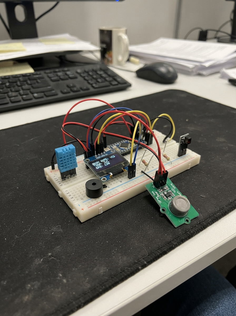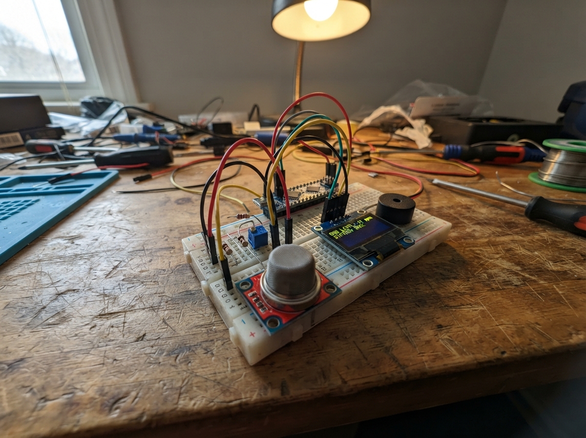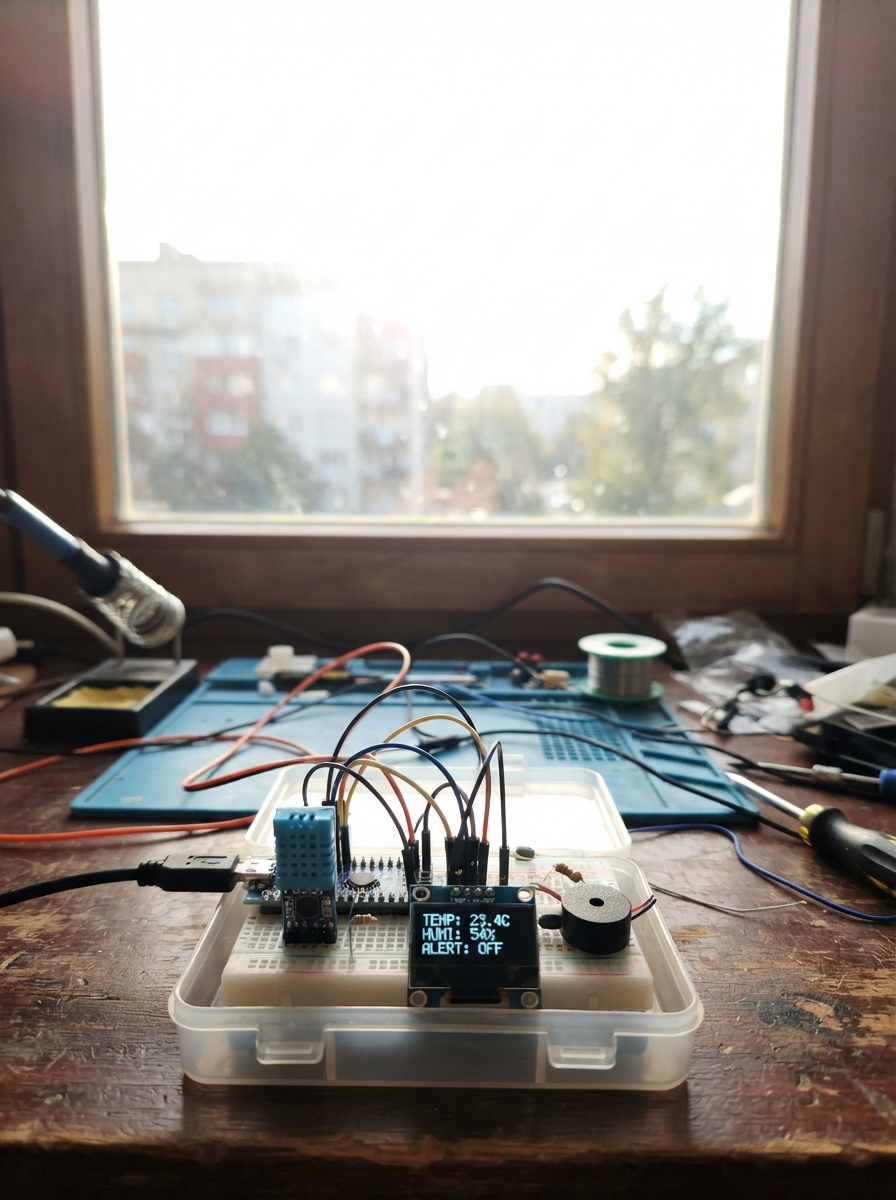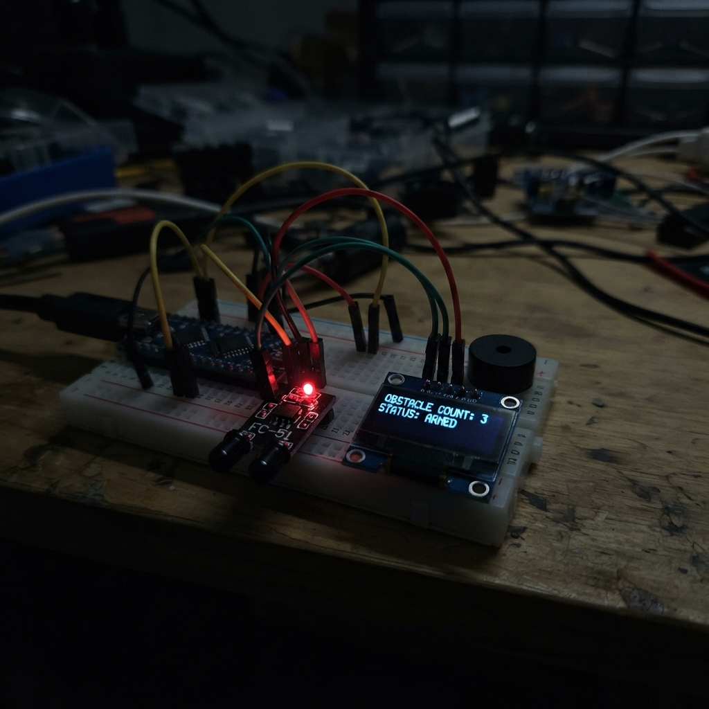
This obstacle counter alarm uses an ESP32 to detect objects passing by an infrared sensor and display a running count on an OLED screen. When the count reaches 10, the piezo buzzer sounds a triple-beep alarm; otherwise, each detection triggers a single beep. The guide includes a complete wiring diagram, parts list, and step-by-step assembly instructions to get the system up and running.
Builders will learn how to interface the FC-51 IR sensor with the ESP32, drive an SSD1306 OLED display via I2C, and control a piezo buzzer for audio feedback. The included firmware handles edge detection to count only new obstacles and provides adjustable sensitivity tuning so the sensor works reliably in different lighting conditions.
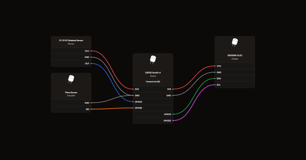
Wiring diagram
Gather all the parts
Assemble it in 4 steps
1. Connect the screen with USB unplugged
Connect OLED VCC to 3V3 and GND to GND. Connect SDA to GPIO21 (data) and SCL to GPIO22 (clock).
- Check the printed pin labels; swapping VCC and GND can damage the screen.
2. Connect the obstacle sensor
Use an FC-51 three-pin sensor. Connect VCC to 3V3, GND to GND, and OUT to GPIO14 (detection signal).
- Do not power this sensor from 5 V here: its output could damage the ESP32 input.
3. Connect the piezo buzzer
Connect the passive piezo buzzer's SIG lead to GPIO18 (tone signal) and the other lead to GND. Use the specified piezo, not a magnetic buzzer or speaker.
4. Adjust detection
After powering the board, turn the sensor's adjustment screw until its detection light responds to an object at your chosen distance. Move the object fully away between counts. Press EN on the board to restart the count.
- The counter stops at 10 and sounds a one-second alert. Bright sunlight and reflective surfaces can affect detection.
Review all connections
1. Connections between "ir1" and "ESP32"
2. Connections between "oled1" and "ESP32"
3. Connections between "buzzer1" and "ESP32"
Deploy the firmware
#include <Arduino.h>
#include <Wire.h>
#include <Adafruit_GFX.h>
#include <Adafruit_SSD1306.h>
#define OLED_ADDR  0x3C
#define IR_PIN     14
#define BUZZER_PIN 18
const int MAX_LIMIT = 10;
int count = 0;
bool prevDetect = false;
Adafruit_SSD1306 display(128, 64, &Wire, -1);

void setup() {
  Serial.begin(115200);
  pinMode(IR_PIN, INPUT);
  pinMode(BUZZER_PIN, OUTPUT);
  digitalWrite(BUZZER_PIN, LOW);
  Wire.begin(21, 22);
  if (!display.begin(SSD1306_SWITCHCAPVCC, OLED_ADDR)) {
    Serial.println("OLED initialization failed");
    while (true) delay(100);
  }
  display.setTextColor(SSD1306_WHITE);
}

void loop() {
  bool detected = (digitalRead(IR_PIN) == LOW); // LOW = obstacle present
  if (detected && !prevDetect) {
    count++;
    if (count >= MAX_LIMIT) {
      for (int i = 0; i < 3; i++) { tone(BUZZER_PIN, 2500, 150); delay(200); }
    } else {
      tone(BUZZER_PIN, 1500, 90); delay(100);
    }
    noTone(BUZZER_PIN);
  }
  prevDetect = detected;

  // Redraw only when the displayed count or sensor state changes.
  static int shownCount = -1;
  static bool shownDetected = false;
  if (count != shownCount || detected != shownDetected) {
    display.clearDisplay();
    display.setTextSize(1); display.setCursor(0, 0);
    display.println("IR PROXIMITY COUNTER");
    display.drawLine(0, 10, 127, 10, SSD1306_WHITE);
    display.setTextSize(2); display.setCursor(0, 18);
    display.printf("CNT:%d/%d", count, MAX_LIMIT);
    display.setTextSize(1);
    display.setCursor(0, 42); display.print(detected ? "STATE: DETECTED" : "STATE: CLEAR");
    display.setCursor(0, 54); display.print(count >= MAX_LIMIT ? "ALERT: LIMIT REACHED!" : "STATUS: MONITORING");
    display.display();
    shownCount = count;
    shownDetected = detected;
  }
  delay(80);
}
Remix this project
Make it yours in one click
Open a full copy of this project in your own Schematik workspace, diagram, code, parts, and assembly steps included. Swap the sensor, add features, or redesign the whole thing with AI. The author's original stays untouched.