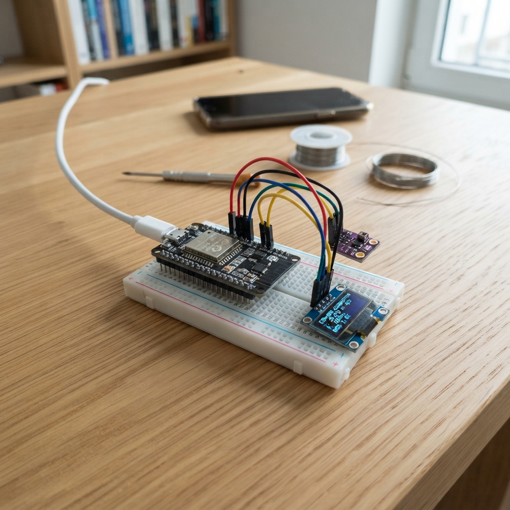
This project creates a wireless sensor aggregation system using ESP-NOW, where one ESP32 acts as a USB-connected receiver collecting data from up to 10 remote sensor nodes. Each remote node transmits 16-bit sensor readings over the 2.4 GHz band with CRC-16 error checking, allowing real-time monitoring of distributed measurements without WiFi infrastructure.
The guide provides a complete wiring diagram, parts list, and step-by-step assembly instructions for preparing the wireless boards and powering the system. Firmware is included for both the central receiver (NODE_ID = 0) and remote sender nodes (NODE_ID 1-10), with configuration details for setting the wireless channel and deploying each board.
Wiring diagram
Assemble it in 2 steps
1. Prepare the wireless boards
Use eleven ESP32 DevKit v1 boards: one receiver and ten independent senders. No wires connect the boards and no sensor modules are needed for random test readings.
2. Power the boards
Connect the receiver to your Windows PC with a USB data cable. Power each sender separately through its USB connector. Keep the boards near each other for the first test.
- Each sender needs a different number from 1 through 10; label the boards with those numbers.
Deploy the firmware
#include <Arduino.h>
#include <WiFi.h>
#include <esp_now.h>
#include <esp_wifi.h>
#include <esp_system.h>
#include <esp_arduino_version.h>

// 0 = USB receiver. Set 1..10 for each sender, then Deploy that board.
constexpr uint8_t NODE_ID = 0;
constexpr uint8_t CHANNEL = 1;
uint16_t values[10] = {};
portMUX_TYPE mux = portMUX_INITIALIZER_UNLOCKED;
const uint8_t broadcastAddress[6] = {255,255,255,255,255,255};

void receiveData(const uint8_t *data, int len) {
  // Radio packet: signature, node ID, uint16 little-endian.
  if (len != 5 || data[0] != 0x53 || data[1] != 0x31 ||
      data[2] < 1 || data[2] > 10) return;
  uint16_t v = uint16_t(data[3]) | (uint16_t(data[4]) << 8);
  portENTER_CRITICAL(&mux);
  values[data[2]-1] = v;
  portEXIT_CRITICAL(&mux);
}
#if ESP_ARDUINO_VERSION_MAJOR >= 3
void onReceive(const esp_now_recv_info_t *, const uint8_t *data, int len) {
#else
void onReceive(const uint8_t *, const uint8_t *data, int len) {
#endif
  receiveData(data, len);
}
uint16_t crc16(const uint8_t *p, size_t n) {
  // CRC-16/CCITT-FALSE: poly 1021, init FFFF, no reflection, xorout 0.
  uint16_t crc = 0xFFFF;
  while (n--) {
    crc ^= uint16_t(*p++) << 8;
    for (int b=0; b<8; ++b)
      crc = (crc & 0x8000) ? uint16_t((crc << 1)^0x1021) : uint16_t(crc << 1);
  }
  return crc;
}
void setup() {
  static_assert(NODE_ID <= 10, "NODE_ID must be 0..10");
  Serial.begin(115200);
  WiFi.mode(WIFI_STA);
  WiFi.setSleep(false);
  if (esp_wifi_set_channel(CHANNEL, WIFI_SECOND_CHAN_NONE) != ESP_OK ||
      esp_now_init() != ESP_OK) { while (true) delay(1000); }
  if (NODE_ID == 0) {
    if (esp_now_register_recv_cb(onReceive) != ESP_OK) while(true) delay(1000);
  } else {
    esp_now_peer_info_t peer = {};
    memcpy(peer.peer_addr, broadcastAddress, 6);
    peer.channel = CHANNEL;
    peer.ifidx = WIFI_IF_STA;
    peer.encrypt = false;
    if (esp_now_add_peer(&peer) != ESP_OK) while(true) delay(1000);
    delay(NODE_ID*31);
  }
}
void loop() {
  static uint32_t last = 0;
  uint32_t now = millis();
  if (uint32_t(now-last) < 100) { delay(1); return; }
  last = now;
  if (NODE_ID) {
    uint16_t v = uint16_t(esp_random());
    uint8_t packet[5] = {0x53,0x31,NODE_ID,uint8_t(v),uint8_t(v>>8)};
    esp_now_send(broadcastAddress, packet, sizeof(packet));
  } else {
    uint8_t frame[26] = {0xDE,0xAD};
    portENTER_CRITICAL(&mux);
    for (int i=0;i<10;++i) {
      frame[2+i*2] = uint8_t(values[i]);
      frame[3+i*2] = uint8_t(values[i]>>8);
    }
    portEXIT_CRITICAL(&mux);
    uint16_t crc = crc16(frame+2,20);
    frame[22] = uint8_t(crc); frame[23] = uint8_t(crc>>8);
    frame[24] = 0xBE; frame[25] = 0xEF;
    Serial.write(frame,sizeof(frame));
  }
}
Remix this project
Make it yours in one click
Open a full copy of this project in your own Schematik workspace, diagram, code, parts, and assembly steps included. Swap the sensor, add features, or redesign the whole thing with AI. The author's original stays untouched.