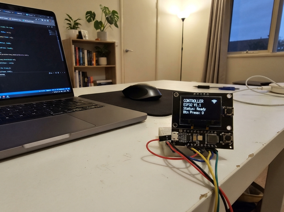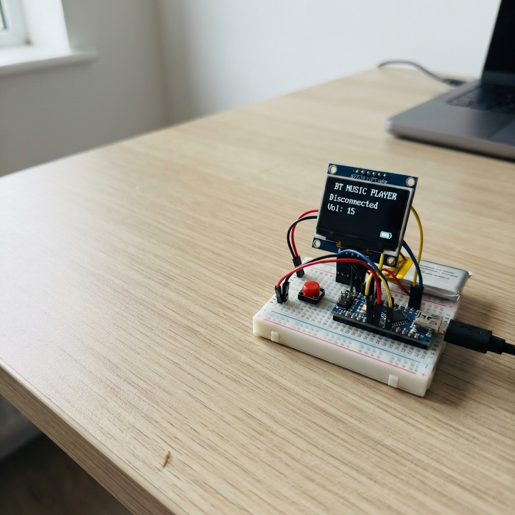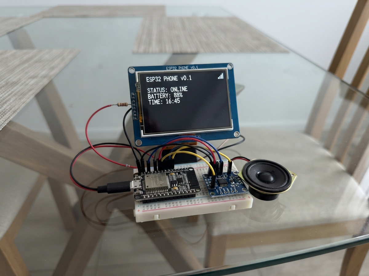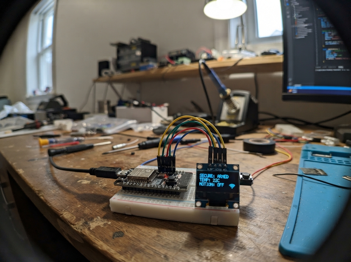
This ESP32-based Wi-Fi security monitor scans for nearby wireless networks and displays the results on a small OLED screen. The device shows the signal strength and security status of detected networks, helping users identify open or weak networks in their environment. A push button triggers manual scans on demand, while the device also performs automatic scans at regular intervals.
Builders will receive a complete wiring diagram showing how to connect the 0.96" OLED display and push button to the ESP32, a full parts list, ready-to-upload firmware with network scanning and display logic, and step-by-step assembly instructions from breadboard prototype through to a 3D-printed enclosure. The guide covers testing procedures to verify the display and button before soldering components permanently.
Wiring diagram
Gather all the parts
Assemble it in 6 steps
1. Prepare the board and display
Solder straight header pins onto the ESP32 DevKit board and the OLED display if they did not arrive with pins fitted. Place both on a breadboard first, with the OLED labels facing upward so you can read VCC, GND, SCL, and SDA.
- Use a small amount of solder: each pin should look like a smooth shiny cone, not a ball bridging two pins.
- Do not permanently solder the display to stripboard until the USB-powered breadboard test is successful.
- Do not swap the OLED VCC and GND wires; swapped power can damage the display.
2. Wire the small screen
Use four short jumper wires: OLED VCC to the ESP32 3V3 pin (power), OLED GND to an ESP32 GND pin (ground), OLED SDA to GPIO21 (data), and OLED SCL to GPIO22 (clock). Read the printed labels on your OLED because the order of the four header pins differs between visually similar displays.
- Red for 3V3 and black for GND makes later fault-finding much easier.
- Keep the two data wires short and away from the USB connector where possible.
3. Add the scan button
Push the tactile button across the center gap of the breadboard so its two sides are not already joined. Run one wire from one button side to GPIO27 (signal) and one wire from the opposite side to an ESP32 GND pin (ground). The program provides the needed internal pull-up, so no extra resistor is required.
- A four-legged tactile button has two legs on each side already connected together; use one leg from each opposite side.
- After power-up, pressing the button should start a new scan rather than holding a signal permanently low.
- Do not use GPIO0, GPIO2, or GPIO12 for this button; those pins affect starting the ESP32 and can prevent it from booting.
4. Test before permanent soldering
With the board resting on a non-metal surface, plug the ESP32 into USB power. The display should show the monitor title, then a nearby Wi-Fi list. Press the added button once to request another scan. Unplug USB before changing any wire.
- If the screen stays blank, first check the four OLED labels and make sure it is powered from 3V3, not a loose wire.
- A network called <hidden> is normal: it means that network does not broadcast its name.
5. Make the permanent version
When the breadboard test works, cut a small piece of perforated stripboard, solder the ESP32 on socket headers so it can be removed, and solder the OLED and button connections exactly as tested. Use insulated wire for every link and trim sharp wire ends on the underside.
- Socket headers let you replace the ESP32 without desoldering the entire project.
- Check each solder joint with a magnifier before applying USB power.
6. Print and fit the case
Print a simple two-piece case with a 29 by 29 mm front window for the OLED, a 7 mm hole for the button, and an opening for the ESP32 USB connector. Mount the display behind the window with small screws, hot glue, or double-sided foam tape, then secure the board so no bare solder joints can touch one another.
- Print a thin front-panel test piece first to confirm that the display window and button hole fit your actual parts.
- PLA at 0.2 mm layers is sufficient for an indoor desk enclosure.
- Keep the USB opening clear so plugging in the cable does not bend the board or stress solder joints.
Review all connections
1. Connections between "oled_1" and "ESP32"
2. Connections between "scan_button" and "ESP32"
Deploy the firmware
#include <Arduino.h>
#include <WiFi.h>
#include <Wire.h>
#include <Adafruit_GFX.h>
#include <Adafruit_SSD1306.h>

constexpr int OLED_SDA_PIN = 21;
constexpr int OLED_SCL_PIN = 22;
constexpr int SCAN_BUTTON_PIN = 27;
constexpr uint8_t SCREEN_WIDTH = 128;
constexpr uint8_t SCREEN_HEIGHT = 64;
constexpr unsigned long AUTO_SCAN_INTERVAL_MS = 60000UL;
constexpr unsigned long BUTTON_DEBOUNCE_MS = 35UL;
constexpr int MAX_SHOWN_NETWORKS = 3;

Adafruit_SSD1306 display(SCREEN_WIDTH, SCREEN_HEIGHT, &Wire, -1);

String networkNames[MAX_SHOWN_NETWORKS];
int networkRssi[MAX_SHOWN_NETWORKS];
bool networkOpen[MAX_SHOWN_NETWORKS];
int shownNetworks = 0;
int totalNetworks = 0;
int openNetworks = 0;
unsigned long lastScanMs = 0;
unsigned long lastButtonChangeMs = 0;
bool lastButtonReading = HIGH;
bool stableButtonState = HIGH;

String shortName(const String &name) {
  if (name.length() == 0) {
    return String("<hidden>");
  }
  if (name.length() <= 12) {
    return name;
  }
  return name.substring(0, 11) + ".";
}

void drawStatus(const String &line1, const String &line2 = "") {
  display.clearDisplay();
  display.setTextColor(SSD1306_WHITE);
  display.setTextSize(1);
  display.setCursor(0, 0);
  display.println("Wi-Fi Safety Monitor");
  display.drawFastHLine(0, 10, SCREEN_WIDTH, SSD1306_WHITE);
  display.setCursor(0, 18);
  display.println(line1);
  if (line2.length() > 0) {
    display.setCursor(0, 34);
    display.println(line2);
  }
  display.display();
}

void drawResults() {
  display.clearDisplay();
  display.setTextColor(SSD1306_WHITE);
  display.setTextSize(1);
  display.setCursor(0, 0);
  display.printf("Found %d | Open %d", totalNetworks, openNetworks);
  display.drawFastHLine(0, 10, SCREEN_WIDTH, SSD1306_WHITE);

  for (int i = 0; i < shownNetworks; ++i) {
    int y = 14 + (i * 16);
    display.setCursor(0, y);
    display.print(shortName(networkNames[i]));
    display.setCursor(78, y);
    display.print(networkRssi[i]);
    display.print("dB");
    display.setCursor(0, y + 8);
    display.print(networkOpen[i] ? "OPEN" : "LOCKED");
  }

  if (shownNetworks == 0) {
    display.setCursor(0, 24);
    display.println("No networks found");
  }
  display.display();
}

void scanNetworks() {
  drawStatus("Scanning nearby Wi-Fi...", "Observation only");
  int found = WiFi.scanNetworks(false, true);

  totalNetworks = found > 0 ? found : 0;
  openNetworks = 0;
  shownNetworks = 0;

  for (int i = 0; i < totalNetworks; ++i) {
    bool isOpen = WiFi.encryptionType(i) == WIFI_AUTH_OPEN;
    if (isOpen) {
      ++openNetworks;
    }
    if (shownNetworks < MAX_SHOWN_NETWORKS) {
      networkNames[shownNetworks] = WiFi.SSID(i);
      networkRssi[shownNetworks] = WiFi.RSSI(i);
      networkOpen[shownNetworks] = isOpen;
      ++shownNetworks;
    }
  }

  WiFi.scanDelete();
  lastScanMs = millis();
  drawResults();
}

void setup() {
  pinMode(SCAN_BUTTON_PIN, INPUT_PULLUP);
  Wire.begin(OLED_SDA_PIN, OLED_SCL_PIN);

  if (!display.begin(SSD1306_SWITCHCAPVCC, 0x3C)) {
    while (true) {
      delay(1000);
    }
  }

  WiFi.mode(WIFI_STA);
  WiFi.disconnect();
  drawStatus("Starting scanner...");
  delay(500);
  scanNetworks();
}

void loop() {
  bool reading = digitalRead(SCAN_BUTTON_PIN);
  unsigned long now = millis();

  if (reading != lastButtonReading) {
    lastButtonChangeMs = now;
  }

  if ((now - lastButtonChangeMs) > BUTTON_DEBOUNCE_MS && reading != stableButtonState) {
    stableButtonState = reading;
    if (stableButtonState == LOW) {
      scanNetworks();
    }
  }
  lastButtonReading = reading;

  if (now - lastScanMs >= AUTO_SCAN_INTERVAL_MS) {
    scanNetworks();
  }

  delay(10);
}
Remix this project
Make it yours in one click
Open a full copy of this project in your own Schematik workspace, diagram, code, parts, and assembly steps included. Swap the sensor, add features, or redesign the whole thing with AI. The author's original stays untouched.