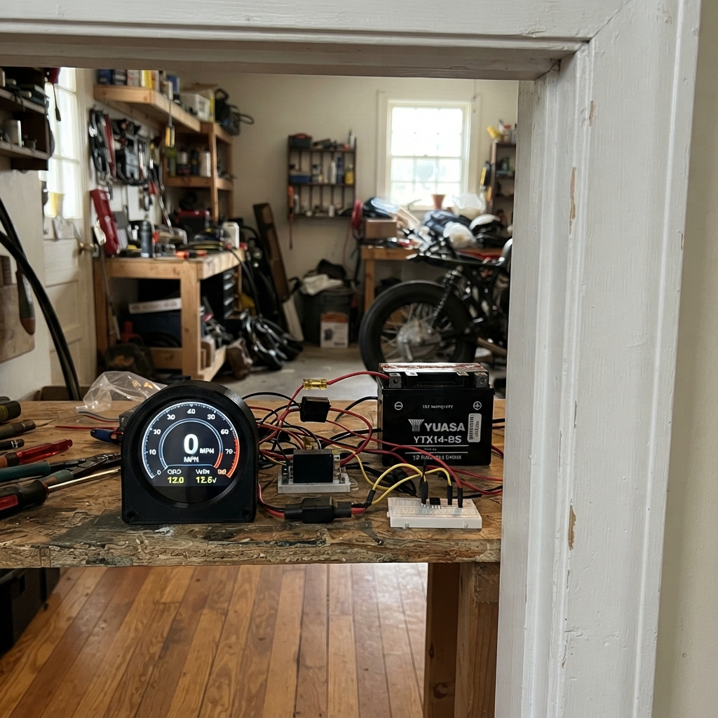
This project transforms a BMW Boxer motorcycle with a Daytona speed pulse converter into a modern digital speedometer using a 4-inch round smart LCD display. The ESP32 microcontroller reads speed pulses from the gearbox-mounted converter, processes them through protective circuitry, and displays real-time speed on the DWIN display with a smooth needle animation.
Builders will receive a complete wiring diagram showing how to integrate the 12V motorcycle battery through a fused supply, step down to 5V logic levels, and safely interface the speed sensor with the display via serial communication. The guide includes the full firmware, assembly instructions for mounting the Daytona converter, and calibration steps to ensure accurate speed readings specific to each motorcycle.
Wiring diagram
Gather all the parts
Assemble it in 7 steps
1. Mount the Daytona converter on the gearbox
Disconnect the motorcycle battery. Remove the original speedometer cable from the gearbox drive and fit daytona_sensor in its place, following the mechanical fitting instructions supplied with the converter. Route its red, black, and yellow wires away from the exhaust and any moving suspension parts.
- Leave a little slack at the gearbox so engine vibration does not pull on the converter cable.
- Do not force the converter onto the gearbox drive; cross-threading can damage the gearbox fitting.
2. Make the fused 12-volt supply
Connect motorcycle_battery POSITIVE to fuse_holder BATTERY, fuse_holder LOAD to fuse IN, and fuse OUT to both buck VIN+ and daytona_sensor RED (power). Connect motorcycle_battery NEGATIVE to buck VIN- and daytona_sensor BLACK (ground). Put the fuse holder close to the battery positive terminal.
- Use an ignition-switched 12 V feed if you want the speedometer to turn off with the key.
- Disconnect the motorcycle battery before crimping wires; a short can heat the wiring or damage the motorcycle electrical system.
3. Set the converter to 5 volts
Keep the ESP32 and display disconnected. Reconnect the motorcycle battery and measure across buck VOUT+ and VOUT-. Adjust buck until the meter reads exactly 5.0 V. Then disconnect the motorcycle battery again. Connect buck VOUT+ to the ESP32 VIN or 5V pin (power) and buck VOUT- to ESP32 GND (ground).
- Use a multimeter with clean probe tips so you do not accidentally bridge two terminals.
- Do not put the buck's 5 V output onto the ESP32 3V3 pin; that can damage the ESP32.
4. Build the protected speed-pulse input
Put pulse_input_resistor between daytona_sensor YELLOW and pulse_opto Anode (pin 1). Connect pulse_opto Cathode (pin 2) to daytona_sensor BLACK. Connect pulse_opto Emitter (pin 3) to ESP32 GND. Connect pulse_opto Collector (pin 4) to ESP32 GPIO16 (speed signal). Finally, connect pulse_pullup_resistor between ESP32 3V3 and pulse_opto Collector/pin 4.
- On a PC817 viewed from above with its notch upward, pin 1 is the upper-left pin. Mark the pin-1 end before soldering.
- Use heat-shrink tubing or an insulated small perfboard; this circuit must not touch the motorcycle frame.
- Never connect the Daytona yellow wire directly to GPIO16; the motorcycle signal can damage the ESP32 input.
5. Wire the round screen through the level converter
Connect display VCC to buck VOUT+ (5 V power) and display GND to ESP32 GND (ground). Connect display_level_shifter LV to ESP32 3V3 (power), HV to buck VOUT+ (5 V power), and GND to ESP32 GND (ground). Connect its LV1 channel wire to ESP32 GPIO17 (screen data), then connect the matching HV1 channel wire to display RX (screen data).
- Use the display's supplied cable and read the labels on the connector; do not guess pin order.
- Make sure VCC and GND are not swapped, because swapped power can damage the display.
6. Calibrate the displayed speed
After deployment, ride at a steady speed and compare the display with a trusted reference on a safe closed road. If the display says 80 km/h while the reference says 60 km/h, change PULSES_PER_KM in the firmware from 1000 to 1333: multiply the current number by displayed speed divided by true speed. Deploy again and repeat until it agrees. The initial 1000 value is only a safe starting point because Daytona requires calibration for the individual motorcycle.
- Use a steady speed for the comparison; a short, smooth test run makes the adjustment more reliable.
- Do not try to change settings or look at loose wiring while riding. This is an auxiliary instrument and is not a certified replacement for the original legal speedometer.
7. Secure the electronics
Put the ESP32, pulse_opto, both resistors, buck, fuse holder, and all joins inside a weather-resistant enclosure. Mount the round display in a sealed gauge housing and secure every cable with cable ties and strain relief so vibration cannot pull on a connector.
- Keep the 12 V wiring and the small pulse-input board dry and away from the ignition coil and spark-plug leads.
- A loose wire can short against the frame and stop the display or damage motorcycle wiring.
Review all connections
1. Connections between "fuse_holder" and "ESP32"
2. Connections between "fuse" and "ESP32"
3. Connections between "buck" and "ESP32"
4. Connections between "motorcycle_battery" and "ESP32"
5. Connections between "display" and "ESP32"
6. Connections between "display_level_shifter" and "ESP32"
7. Connections between "daytona_sensor" and "ESP32"
8. Connections between "pulse_input_resistor" and "ESP32"
9. Connections between "pulse_opto" and "ESP32"
10. Connections between "pulse_pullup_resistor" and "ESP32"
Deploy the firmware
#include <Arduino.h>

constexpr int SPEED_PULSE_PIN = 16;
constexpr int DISPLAY_TX_PIN = 17;
constexpr uint32_t DISPLAY_BAUD = 115200;
constexpr int MAX_SPEED_KMH = 180;

// Set this after the road calibration specified in the assembly instructions.
// The initial value is only a starting point; it is not a BMW-specific calibration.
constexpr float PULSES_PER_KM = 1000.0f;
constexpr uint32_t SPEED_SAMPLE_MS = 250;
constexpr uint32_t STOP_TIMEOUT_MS = 1500;
constexpr uint32_t MIN_PULSE_GAP_US = 1000;

// Variable addresses used by the DMG72720C040_03WTC DGUS speedometer profile.
constexpr uint16_t SPEED_VP = 0x1000;
constexpr uint16_t SENSOR_OK_VP = 0x1002;
constexpr uint16_t NEEDLE_VP = 0x1004;

HardwareSerial displaySerial(1);
volatile uint32_t pulseCount = 0;
volatile uint32_t lastPulseUs = 0;
volatile uint32_t lastPulseMs = 0;

int shownSpeed = -1;
bool shownSensor = false;

void IRAM_ATTR countSpeedPulse() {
  const uint32_t nowUs = micros();
  if (nowUs - lastPulseUs >= MIN_PULSE_GAP_US) {
    pulseCount++;
    lastPulseUs = nowUs;
    lastPulseMs = millis();
  }
}

void writeDgusWord(uint16_t address, uint16_t value) {
  const uint8_t frame[] = {
    0x5A, 0xA5, 0x05, 0x82,
    static_cast<uint8_t>(address >> 8), static_cast<uint8_t>(address & 0xFF),
    static_cast<uint8_t>(value >> 8), static_cast<uint8_t>(value & 0xFF)
  };
  displaySerial.write(frame, sizeof(frame));
}

void showSpeed(int speed) {
  speed = constrain(speed, 0, MAX_SPEED_KMH);
  if (speed == shownSpeed) return;

  const uint16_t needleAngle = static_cast<uint16_t>(1350L + (2700L * speed) / MAX_SPEED_KMH);
  writeDgusWord(SPEED_VP, static_cast<uint16_t>(speed));
  writeDgusWord(NEEDLE_VP, needleAngle);
  shownSpeed = speed;
}

void showSensorStatus(bool hasRecentPulse) {
  if (hasRecentPulse == shownSensor && shownSpeed != -1) return;
  writeDgusWord(SENSOR_OK_VP, hasRecentPulse ? 1 : 0);
  shownSensor = hasRecentPulse;
}

void setup() {
  Serial.begin(115200);
  pinMode(SPEED_PULSE_PIN, INPUT_PULLUP);
  attachInterrupt(digitalPinToInterrupt(SPEED_PULSE_PIN), countSpeedPulse, FALLING);
  displaySerial.begin(DISPLAY_BAUD, SERIAL_8N1, -1, DISPLAY_TX_PIN);
  showSpeed(0);
  showSensorStatus(false);
}

void loop() {
  static uint32_t previousSampleMs = millis();
  const uint32_t nowMs = millis();
  const uint32_t elapsedMs = nowMs - previousSampleMs;

  if (elapsedMs >= SPEED_SAMPLE_MS) {
    noInterrupts();
    const uint32_t countedPulses = pulseCount;
    pulseCount = 0;
    const uint32_t pulseAgeMs = nowMs - lastPulseMs;
    interrupts();

    previousSampleMs = nowMs;
    const bool hasRecentPulse = pulseAgeMs <= STOP_TIMEOUT_MS;
    const float speedKmh = (countedPulses * 3600000.0f) / (PULSES_PER_KM * elapsedMs);
    showSensorStatus(hasRecentPulse);
    showSpeed(hasRecentPulse ? lroundf(speedKmh) : 0);
  }

  delay(5);
}
Remix this project
Make it yours in one click
Open a full copy of this project in your own Schematik workspace, diagram, code, parts, and assembly steps included. Swap the sensor, add features, or redesign the whole thing with AI. The author's original stays untouched.