Community project
Ethernet Audio Streamer
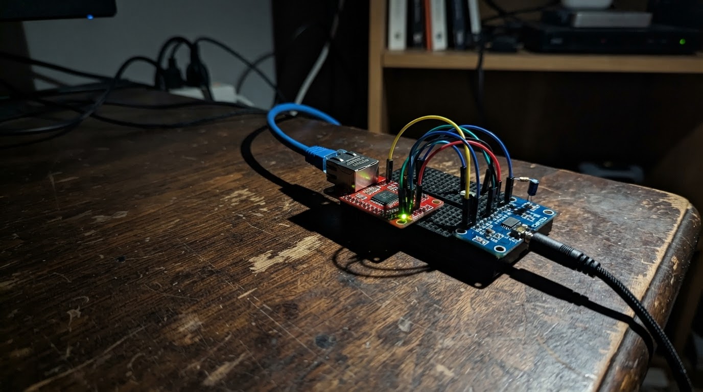
This project builds a network audio streamer that receives RTP audio packets over Ethernet and outputs stereo sound through a 3.5 mm jack. The ESP32 microcontroller connects to a wired network via the W5500 Ethernet module and feeds audio data to a PCM5102A stereo DAC, enabling high-quality audio streaming from compatible sources on the local network.
The guide provides a complete parts list, wiring diagram showing all SPI and I2S connections, step-by-step assembly instructions, and Arduino firmware that handles Ethernet configuration, RTP packet reception, and I2S audio output at 48 kHz. Builders will have a working audio streamer capable of receiving network audio streams and converting them to line-level output.
Wiring diagram

Gather all the parts
Assemble it in 5 steps
1. Keep the board unpowered while wiring
Place the ESP32 DevKit, W5500 Ethernet module, PCM5102A DAC board, and 3.5 mm jack where their printed pin labels are easy to see. Leave the ESP32 USB cable unplugged until every wire is checked.
- Do not connect or remove signal wires while the board is powered; a loose wire can short two pins together.
2. Wire the Ethernet module
Connect the W5500 VCC pin to ESP32 3V3 (power), W5500 GND to ESP32 GND (ground), MOSI to GPIO23 (data), MISO to GPIO19 (data), SCK to GPIO18 (clock), CS to GPIO4 (device-select), and RST to GPIO13 (reset). Plug the W5500 RJ45 socket into your Ethernet switch or router with a normal Ethernet cable.
- Keep the SPI wires short, especially the SCK wire, to make the network connection more reliable.
- Make sure the W5500 module is a 3.3 V-compatible version before connecting VCC; applying the wrong supply voltage can damage it.
3. Wire the audio converter
Connect PCM5102A VCC to ESP32 3V3 (power), PCM5102A GND to ESP32 GND (ground), BCK to GPIO27 (audio timing), LCK to GPIO26 (left/right timing), and DIN to GPIO25 (audio data).
- The DAC and Ethernet module must share the same ESP32 GND pin or ground rail, otherwise the audio data has no reliable reference.
- Make sure VCC and GND are not swapped — swapped power can damage the DAC board.
4. Connect the line output jack
Connect the DAC LOUT pin to the 3.5 mm jack TIP contact (left audio), DAC ROUT to the jack RING contact (right audio), and the jack SLEEVE contact to ESP32 GND (audio ground). Connect this jack to powered speakers, an amplifier line input, or other line-level equipment—not directly to passive speakers.
- This output is line level and cannot safely power an unamplified speaker by itself.
5. Check and power the streamer
Check each wire against its printed label, then plug the ESP32 into USB for power. The board receives RTP/L16, 48 kHz, 16-bit stereo packets sent to 192.168.1.50 on UDP port 5004 and sends them to the audio jack.
- Set the sending computer or audio source to the same Ethernet network and use a compatible RTP/L16 stereo stream.
Review all connections
1. Connections between "w5500_1" and "ESP32"
2. Connections between "dac_1" and "ESP32"
3. Connections between "line_out_1" and "ESP32"
Deploy the firmware
#include <Arduino.h>
#include <SPI.h>
#include <Ethernet.h>
#include <EthernetUdp.h>
#include <driver/i2s.h>


// Forward declarations
void setupI2S();
void setupEthernet();
void playRtpPacket(int packetSize);

constexpr int ETH_CS_PIN = 4;
constexpr int ETH_RST_PIN = 13;
constexpr int ETH_SCK_PIN = 18;
constexpr int ETH_MISO_PIN = 19;
constexpr int ETH_MOSI_PIN = 23;
constexpr int I2S_BCK_PIN = 27;
constexpr int I2S_LRCK_PIN = 26;
constexpr int I2S_DOUT_PIN = 25;
constexpr uint16_t RTP_PORT = 5004;
constexpr size_t MAX_UDP_PACKET = 1472;

byte macAddress[] = {0x02, 0xA0, 0x10, 0x00, 0x00, 0x50};
IPAddress localIp(192, 168, 1, 50);
EthernetUDP rtpUdp;
uint8_t packetBuffer[MAX_UDP_PACKET];
int16_t audioBuffer[MAX_UDP_PACKET / 2];

void setupI2S() {
  i2s_config_t config = {};
  config.mode = (i2s_mode_t)(I2S_MODE_MASTER | I2S_MODE_TX);
  config.sample_rate = 48000;
  config.bits_per_sample = I2S_BITS_PER_SAMPLE_16BIT;
  config.channel_format = I2S_CHANNEL_FMT_RIGHT_LEFT;
  config.communication_format = I2S_COMM_FORMAT_STAND_I2S;
  config.intr_alloc_flags = ESP_INTR_FLAG_LEVEL1;
  config.dma_buf_count = 8;
  config.dma_buf_len = 256;
  config.use_apll = false;
  config.tx_desc_auto_clear = true;
  config.fixed_mclk = 0;
  i2s_driver_install(I2S_NUM_0, &config, 0, nullptr);

  i2s_pin_config_t pins = {};
  pins.bck_io_num = I2S_BCK_PIN;
  pins.ws_io_num = I2S_LRCK_PIN;
  pins.data_out_num = I2S_DOUT_PIN;
  pins.data_in_num = I2S_PIN_NO_CHANGE;
  i2s_set_pin(I2S_NUM_0, &pins);
  i2s_zero_dma_buffer(I2S_NUM_0);
}

void setupEthernet() {
  pinMode(ETH_RST_PIN, OUTPUT);
  digitalWrite(ETH_RST_PIN, LOW);
  delay(20);
  digitalWrite(ETH_RST_PIN, HIGH);
  delay(100);

  SPI.begin(ETH_SCK_PIN, ETH_MISO_PIN, ETH_MOSI_PIN, ETH_CS_PIN);
  Ethernet.init(ETH_CS_PIN);
  Ethernet.begin(macAddress, localIp);
  rtpUdp.begin(RTP_PORT);
}

void playRtpPacket(int packetSize) {
  if (packetSize < 12 || packetSize > (int)sizeof(packetBuffer)) return;
  int received = rtpUdp.read(packetBuffer, packetSize);
  if (received != packetSize) return;

  const uint8_t version = packetBuffer[0] >> 6;
  const bool hasExtension = (packetBuffer[0] & 0x10) != 0;
  const uint8_t csrcCount = packetBuffer[0] & 0x0F;
  if (version != 2) return;

  size_t offset = 12 + (size_t)csrcCount * 4;
  if (offset > (size_t)received) return;
  if (hasExtension) {
    if (offset + 4 > (size_t)received) return;
    const uint16_t extensionWords = ((uint16_t)packetBuffer[offset + 2] << 8) | packetBuffer[offset + 3];
    offset += 4 + (size_t)extensionWords * 4;
  }
  if (offset >= (size_t)received) return;

  size_t payloadBytes = (size_t)received - offset;
  payloadBytes &= ~((size_t)3); // Whole 16-bit left/right sample pairs only.
  if (payloadBytes == 0 || payloadBytes / 2 > sizeof(audioBuffer) / sizeof(audioBuffer[0])) return;

  for (size_t i = 0; i < payloadBytes / 2; ++i) {
    audioBuffer[i] = (int16_t)(((uint16_t)packetBuffer[offset + i * 2] << 8) |
                               packetBuffer[offset + i * 2 + 1]);
  }

  size_t written = 0;
  i2s_write(I2S_NUM_0, audioBuffer, payloadBytes, &written, portMAX_DELAY);
}

void setup() {
  Serial.begin(115200);
  setupI2S();
  setupEthernet();
  Serial.println("AoIP receiver ready: RTP/L16 stereo, 48 kHz, UDP port 5004, IP 192.168.1.50");
}

void loop() {
  int packetSize = rtpUdp.parsePacket();
  if (packetSize > 0) playRtpPacket(packetSize);
}
Remix this project
Make it yours in one click
Open a full copy of this project in your own Schematik workspace — diagram, code, parts, and assembly steps included. Swap the sensor, add features, or redesign the whole thing with AI. The author's original stays untouched.