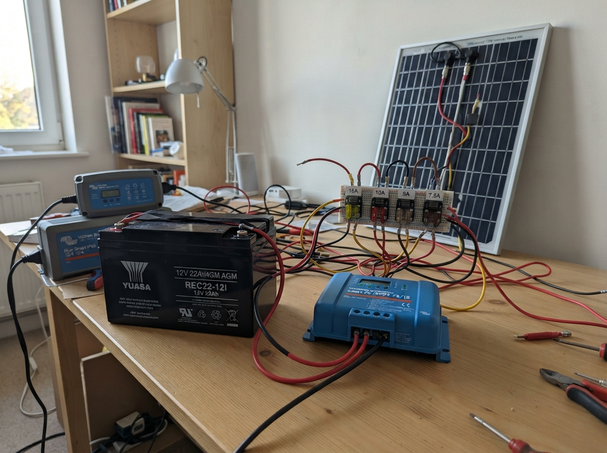
This guide builds a solar-powered backup power system with automatic sun tracking to maximize energy harvest. The system combines a 100W solar panel, MPPT charge controller, 22Ah AGM battery, and inverter to provide 230V AC backup power, with an Arduino-based dual-axis tracker that follows the sun throughout the day and a thermal management system to keep components safe.
Builders will receive a complete wiring diagram showing battery, charge controller, inverter, and protection circuits; a detailed parts list with fuse ratings for each circuit; Arduino firmware for sun tracking via dual-axis servos and temperature monitoring via DS18B20 sensors; and step-by-step assembly instructions covering system planning, battery placement, charge path setup, load distribution, and tracker calibration.
Wiring diagram
Gather all the parts
Assemble it in 13 steps
1. حدود النظام قبل شراء القطع
النظام يشغل راوتر 12V حتى 1A ولمبة DC 5W وشاحن USB 5V حتى 2A. راجع ملصق الراوتر ومقاس الفيشة وقطبيتها. لا تستخدمه مع راوتر 9V أو PoE. البطارية AGM سعة 22Ah بدلاً من تجميع خلايا ليثيوم. التشغيل التقريبي 3–4 ساعات عند حمل إجمالي حوالي 30W وبطارية جديدة مشحونة، وليس ضماناً.
- لا توصل أي خرج بمقبس البيت أو بلوحة الكهرباء. هذا ليس نظام تغذية للمنزل كله.
2. تجهيز مكان البطارية والشحن
ضع البطارية قائمة في مكان داخلي جاف ومهوّى بعيد عن الحرارة والشرر والأطفال. ثبّت الشاحن الأصلي المغلق قرب مقبس محمي بقاطع تسرب أرضي. لا تفتح الشاحن ولا تعدّل كابل 230V. افصل فيش الكهرباء وافتح قاطع اللوح وانزع الفيوز الرئيسي قبل التوصيل.
- AGM قد تطلق غازاً عند العطل. لا تستخدم صندوقاً محكم الغلق. البطارية قادرة على صهر الأسلاك عند القصر.
3. مسار البطارية والشواحن
موجب البطارية إلى فيوز 15A على مسافة أقل من 15 سم ثم تفرّع: فيوز 10A إلى BAT+ في MPPT، وفيوز 5A إلى موجب شاحن الحائط. سالب الشاحن وسالب البطارية إلى BAT- في MPPT. لا تربط سالب الأحمال مباشرة بسالب البطارية؛ استخدم LOAD-. استخدم أطراف كبس مغطاة وكابل نحاس 2.5 مم² للمسار الرئيسي القصير حتى متر؛ راجع المقاس للمسارات الأطول.
4. إعداد الشحن والحماية قبل توصيل الشمس
وصّل البطارية أولاً. في VictronConnect اضبط MPPT على 12V وAGM: حد الشحن 3A، امتصاص 14.4V، تعويم 13.65V، إلغاء equalization. شاحن IP65 12/4 على Normal وLow current 2A وإلغاء recondition. اضبط تعويض الحرارة بحسب Yuasa ودرجة مكان البطارية، وليس حرارة اللوح. اضبط LOAD فصل 12.1V وعودة 12.7V؛ هذه حماية محافظة وليست قياساً لنسبة الشحن. تحقق أن الجمبر لا يلغي إعداد LOAD. مجموع الشحن لا يزيد عن 5A مقابل حد البطارية 5.5A.
- لا تشغّل الشاحنين بالإعدادات الافتراضية دون ضبط حدود التيار. عند حرارة بطارية خارج حدود الشركة أوقف الشحن.
5. توصيل اللوح
مع فتح قاطع الشمس: موجب اللوح إلى قاطع PV ثم PV+، والسالب إلى PV-. اختر لوح 100W، جهد تشغيل 18–22V وجهد دائرة مفتوحة أقل من 30V وتيار قصر أقل من 8A. استخدم سلك شمسي خارجي وموصلات متطابقة القطبية. بعد إعداد البطارية أغلق القاطع. للفصل افتح PV أولاً ثم افصل البطارية.
- اللوح يولد كهرباء بمجرد الإضاءة. غطّه أثناء التركيب.
6. توزيع الأحمال المحمية
خرج LOAD+ يغذّي كل فرع عبر فيوزه المحدد في الرسم. كل سالب حمل يعود إلى LOAD-، وهو GND للتحكم. منظم الراوتر يحافظ على 12V رغم تغيّر جهد البطارية. لا توصل الراوتر أو المراوح مباشرة بجهد الشحن. وصّل اللمبة النهائية ذات تنظيم التيار الداخلي وشاحن السيارة USB كما بالرسم؛ اشحن الهاتف من منفذ USB الأصلي فقط.
7. تغذية التحكم
من LOAD+ عبر فيوز logicf إلى VIN لمحول MP1584. اضبط خرجه بملتيميتر إلى 5.00V قبل توصيله بطرف 5V في Uno. سالب المحول إلى GND. أثناء توصيل USB للبرمجة افصل سلك خرج 5V الخارجي عن Uno لمنع تغذية USB عكسياً؛ أعده بعد فصل USB.
- لا تدخل جهد البطارية إلى طرف 5V. استخدم أطراف تثبيت للقدرة، وليس لوحة تجارب.
8. تبريد خلف اللوح
ثبّت المروحتين تحت اللوح مع قناة هواء وفاصل 5–10 سم وشبك حماية، دون حفر ظهر اللوح أو تغطية الخلايا. موجب المراوح من منظم fanreg بجهد 12V عبر فيوز fanf؛ أسود المراوح إلى DRAIN في MOSFET وSOURCE إلى GND. D9 عبر مقاومة 220 أوم إلى GATE؛ مقاومة 10k من GATE إلى GND. الدايود شريطه نحو موجب المراوح. اترك أسلاك قياس السرعة الصفراء معزولة.
- المراوح IP52 لا تتحمل المطر المباشر. التبريد يستهلك طاقة وقد لا يعطي زيادة صافية؛ اختبر فائدته عملياً. لا تستخدم رش مياه.
9. حساس حرارة اللوح
ثبّت حساس DS18B20 على الظهر بمادة عازلة كهربائياً وناقلة للحرارة دون ثقب أو خدش. VCC إلى 3V3 وGND إلى GND وDATA إلى D2. مقاومة 4.7k بين DATA و3V3. طابق أطراف الحساس مع وثيقته ولا تعتمد على لون السلك. البرنامج لا يفعّل رفع داخلي إلى 5V. تشغيل المراوح عند 45° وفصلها عند 38°؛ عطل الحساس يشغّل التبريد احتياطياً.
10. حساسا اتجاه الشمس
كل LDR طرف إلى 5V والآخر إلى A0 للشرق أو A1 للغرب. من كل دخل مقاومة 10k إلى GND. ثبتهما على اللوح على جانبي حاجز ظل صغير عمودي على السطح. هكذا القراءة تزيد مع الضوء. اضبط الحاجز لتقارب القراءتين عند مواجهة الشمس.
11. هيكل التتبع والمحرك
اطلب من فني ميكانيكا تصميم محور واحد متوازن شرق–غرب وميل موسمي ثابت، مع محددات حركة وحواجز للأصابع وقفل تثبيت. استخدم ثقوب إطار اللوح الأصلية، ومفصلات تناسب actuator المحدد، وكابل مرن مرتخٍ لا يلتف. اختيار قوة المحرك لا يغني عن حساب عزم اللوح والرياح وهندسة نقاط التثبيت. اختبر مشوار 6 بوصات قبل توصيله باللوح.
- التصميم ليس معتمداً للتركيب على سطح أو في رياح. لا تثبته بالخارج دون مراجعة أحمال الرياح والتثبيت ومنع السقوط بواسطة مختص. لا توجد حماية رياح آلية أو تتبع بمحورين.
12. توصيل سائق التتبع واختبار الاتجاه
B+ عبر motorf من LOAD+، وB- إلى GND، وVCC إلى 5V وGND إلى GND. M+ إلى أحمر المحرك وM- إلى الأسود. RPWM إلى D5 وLPWM إلى D6 وR_EN إلى D7 وL_EN إلى D8. مفتاح arm: COM إلى GND وNO إلى D4. الحركة مسموحة فقط أثناء إغلاق المفتاح، كل 30 ثانية نبضة 250ms. نهايات مشوار المحرك الداخلية تقطع الحركة. اختبر والمحرك مفصول ميكانيكياً: إضاءة حساس الشرق يجب أن تحرك اللوح شرقاً؛ لو العكس افصل القدرة واعكس سلكي المحرك.
- لا تشغّل بدون مراجعة نهايات المشوار الفعلية. لإيقاف الحركة اترك المفتاح؛ لعطل كهربائي افصل فيوز motorf. لا تعتمد على البرنامج وحده لحماية الأصابع.
13. اختبار الاستمرارية قبل الاعتماد
قِس خرج الراوتر 12V وقطبيته وخرج USB 5V قبل توصيل الأجهزة. ابدأ بالأحمال وحدها والمحرك غير مسموح. جرّب نزع فيشة شاحن الحائط: الأحمال تظل على البطارية بدون تبديل ريلاي. ثم اختبر الشمس وحدها والشاحنين معاً مع التأكد من حدود التيار وحرارة المنظمات. افحص أن فصل LOAD يفصل جميع الأحمال؛ لا تسمح بأي مسار أرضي خارجي يتجاوز LOAD-. سجّل زمن التشغيل الحقيقي قبل الاعتماد عليه.
- الحماية لا تضمن عمراً محدداً للبطارية. لا تعرض البطارية للشمس ولا تترك التشغيل الأول بلا مراقبة.
Review all connections
1. Connections between "battery" and "Arduino"
2. Connections between "mainf" and "Arduino"
3. Connections between "mpptf" and "Arduino"
4. Connections between "wallf" and "Arduino"
5. Connections between "charger" and "Arduino"
6. Connections between "solar" and "Arduino"
7. Connections between "pvbreak" and "Arduino"
8. Connections between "mppt" and "Arduino"
9. Connections between "motorf" and "Arduino"
10. Connections between "driver" and "Arduino"
11. Connections between "routerf" and "Arduino"
12. Connections between "routerreg" and "Arduino"
13. Connections between "fanf" and "Arduino"
14. Connections between "fanreg" and "Arduino"
15. Connections between "router" and "Arduino"
16. Connections between "lampf" and "Arduino"
17. Connections between "lamp" and "Arduino"
18. Connections between "usbf" and "Arduino"
19. Connections between "usb" and "Arduino"
20. Connections between "logicf" and "Arduino"
21. Connections between "logic" and "Arduino"
22. Connections between "fan1" and "Arduino"
23. Connections between "fan2" and "Arduino"
24. Connections between "mos" and "Arduino"
25. Connections between "gate" and "Arduino"
26. Connections between "pulldown" and "Arduino"
27. Connections between "fly" and "Arduino"
28. Connections between "temp" and "Arduino"
29. Connections between "pullup" and "Arduino"
30. Connections between "east" and "Arduino"
31. Connections between "eastr" and "Arduino"
32. Connections between "west" and "Arduino"
33. Connections between "westr" and "Arduino"
34. Connections between "arm" and "Arduino"
Deploy the firmware
#include <Arduino.h>
// DS18B20 single-device, externally powered bus. No external libraries.
const uint8_t TEMP=2, ARM=4, RPWM=5, LPWM=6, REN=7, LEN=8, FAN=9;
uint32_t conversionAt=0, lastTrack=0, pulseAt=0, windowAt=0, lastLog=0;
bool converting=false, moving=false, cooling=true, fault=true;
uint32_t budget=0;
float temperature=0;
void releaseBus(){ pinMode(TEMP,INPUT); } // external 3.3V pullup, never drive HIGH
void lowBus(){digitalWrite(TEMP,LOW);pinMode(TEMP,OUTPUT);}
bool resetBus(){
 lowBus();delayMicroseconds(480);releaseBus();delayMicroseconds(70);
 bool present=!digitalRead(TEMP);delayMicroseconds(410);return present;
}
void writeByte(uint8_t x){for(uint8_t i=0;i<8;i++){
 noInterrupts();lowBus();if(x&1){delayMicroseconds(6);releaseBus();delayMicroseconds(64);}
 else {delayMicroseconds(60);releaseBus();delayMicroseconds(10);}interrupts();x>>=1;
}}
uint8_t readByte(){uint8_t v=0;for(uint8_t i=0;i<8;i++){
 noInterrupts();lowBus();delayMicroseconds(3);releaseBus();delayMicroseconds(10);
 if(digitalRead(TEMP))v|=(1<<i);delayMicroseconds(53);interrupts();}return v;
}
uint8_t crc8(const uint8_t *p,uint8_t n){uint8_t crc=0;while(n--){uint8_t x=*p++;for(uint8_t i=0;i<8;i++){
 uint8_t mix=(crc^x)&1;crc>>=1;if(mix)crc^=0x8C;x>>=1;}}return crc;}
void stopMotor(){analogWrite(RPWM,0);analogWrite(LPWM,0);digitalWrite(REN,LOW);digitalWrite(LEN,LOW);moving=false;}
void setup(){
 for(uint8_t pin=5;pin<=9;pin++){digitalWrite(pin,LOW);pinMode(pin,OUTPUT);}
 pinMode(ARM,INPUT_PULLUP);releaseBus();stopMotor();digitalWrite(FAN,HIGH);
 Serial.begin(9600);Serial.println(F("Solar backup control: hold ARM to permit motion. Check direction without panel first."));
}
void loop(){
 uint32_t now=millis();
 if(!converting){
  if(resetBus()){writeByte(0xCC);writeByte(0x44);converting=true;conversionAt=now;}
  else {fault=true;cooling=true;}
 }else if(now-conversionAt>=800){
  uint8_t data[9];bool ok=resetBus();
  if(ok){writeByte(0xCC);writeByte(0xBE);for(uint8_t i=0;i<9;i++)data[i]=readByte();ok=(crc8(data,8)==data[8]);}
  if(ok){float t=(int16_t)((data[1]<<8)|data[0])/16.0f;
   ok=(t>=-20 && t<=100 && t!=85.0f);
   if(ok){temperature=t;if(t>=45)cooling=true;else if(t<=38)cooling=false;}}
  fault=!ok;if(fault)cooling=true;converting=false;
 }
 digitalWrite(FAN,cooling?HIGH:LOW);
 if(now-windowAt>=900000UL){budget=0;windowAt=now;}
 if(moving && (now-pulseAt>=250 || digitalRead(ARM)!=LOW)){stopMotor();}
 if(!moving && now-lastTrack>=30000UL){
  lastTrack=now;
  int east=analogRead(A0),west=analogRead(A1);
  int sum=east+west,diff=east-west;
  // 10% optical dead band; no motion in darkness or near ADC saturation.
  if(digitalRead(ARM)==LOW && budget<10000 && sum>600 && east<1015 && west<1015 && abs(diff)>sum/10){
   stopMotor();digitalWrite(REN,HIGH);digitalWrite(LEN,HIGH);
   analogWrite(diff>0?RPWM:LPWM,255);pulseAt=now;moving=true;budget+=250;
  }
 }
 if(now-lastLog>=5000){lastLog=now;Serial.print(F("Panel C="));
  if(fault)Serial.print(F("SENSOR FAULT"));else Serial.print(temperature,1);
  Serial.print(F(" cooling="));Serial.print(cooling);Serial.print(F(" motion="));Serial.println(moving);
 }
}
Remix this project
Make it yours in one click
Open a full copy of this project in your own Schematik workspace, diagram, code, parts, and assembly steps included. Swap the sensor, add features, or redesign the whole thing with AI. The author's original stays untouched.