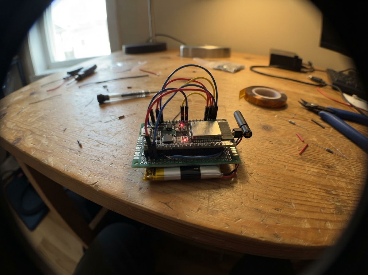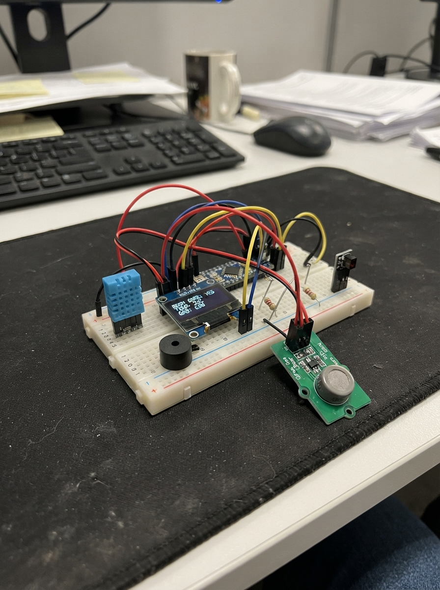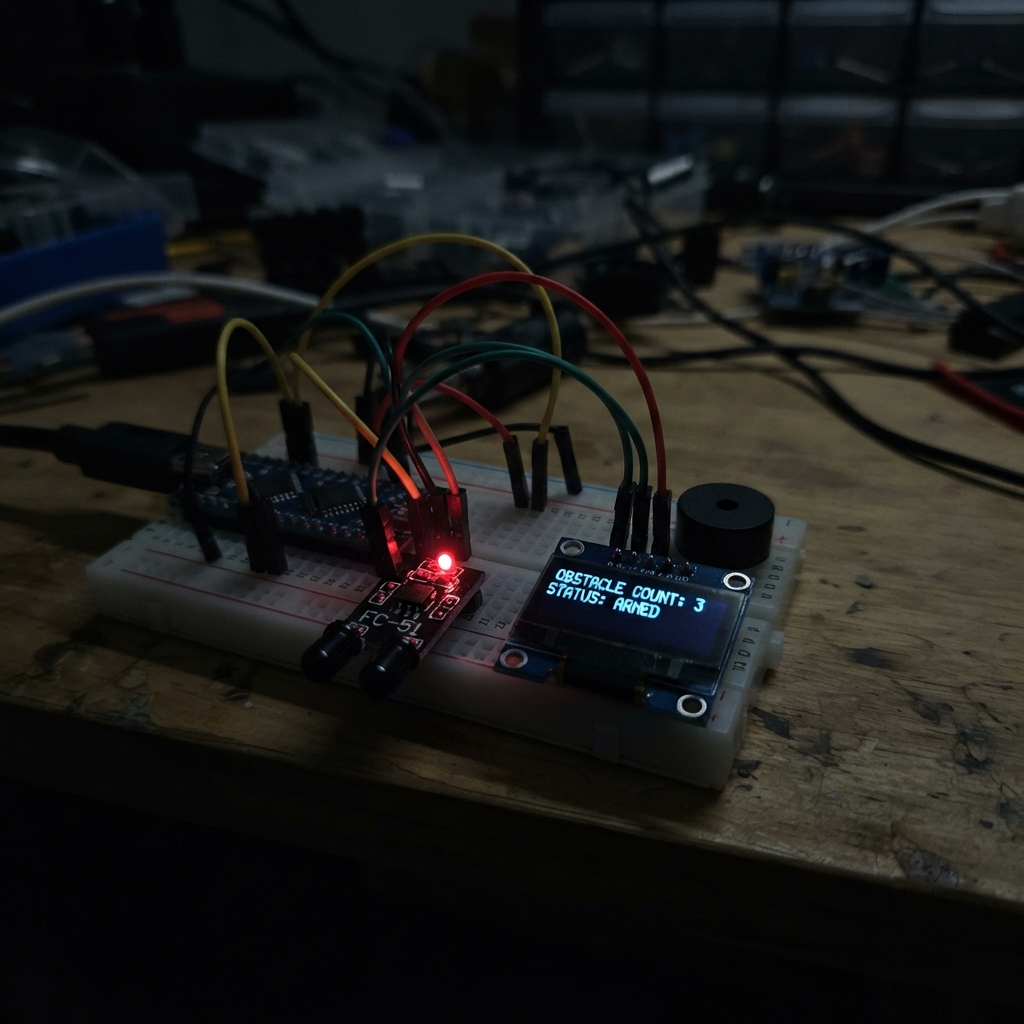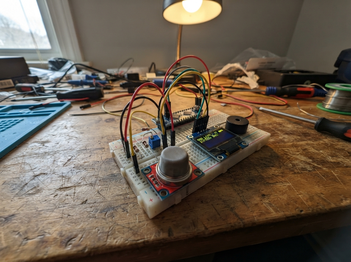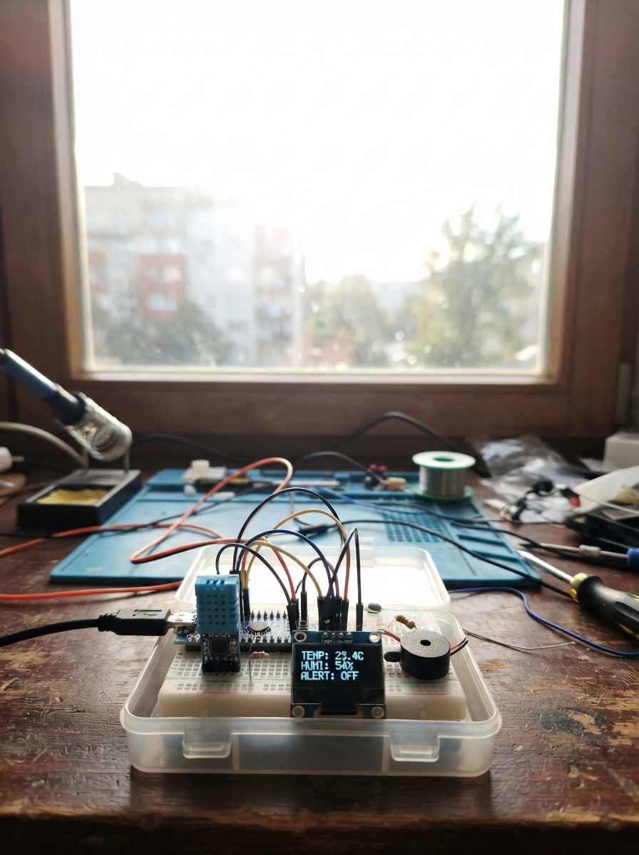
The Environmental Alert Monitor uses an ESP32 microcontroller to continuously measure temperature and humidity with a DHT11 sensor, displaying readings on a small OLED screen. When conditions drift outside safe ranges—temperature above 32°C or below 15°C, or humidity above 80% or below 30%—the system triggers a piezo buzzer to sound an alert.
This guide provides a complete parts list, wiring diagram, and step-by-step assembly instructions to get the monitor running. The included firmware handles sensor reading, threshold detection, and display updates, making it easy to customize alert thresholds for different environments like server rooms, greenhouses, or storage areas.
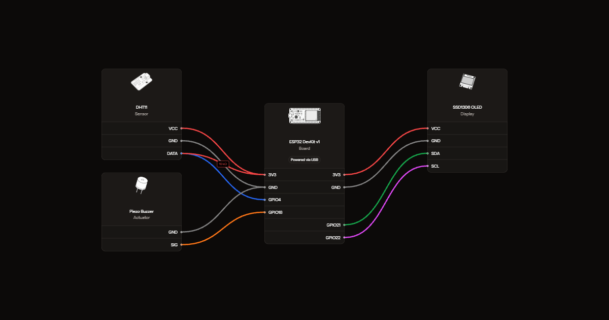
Wiring diagram
Gather all the parts
Assemble it in 5 steps
1. Disconnect power
Unplug USB before wiring the ESP32 DevKit v1. Use the pin labels on each module, not its position.
2. Connect the sensor
Connect DHT11 VCC to 3V3, GND to GND, and DATA to GPIO4. Connect the 10 kΩ resistor between DATA and 3V3 to keep the data line steady when idle.
3. Connect the screen
Connect OLED VCC to 3V3 and GND to GND. Connect SDA to GPIO21 for data and SCL to GPIO22 for the clock.
- Check the printed VCC and GND labels; reversing them can damage the screen.
4. Connect the sounder
Connect one lead of the passive piezo buzzer to GPIO18 and the other to GND. Use the specified passive piezo, not a high-current magnetic buzzer.
5. Check the wiring
Check that all ground wires share ESP32 GND and that both modules receive 3.3 V. Power the board from USB after checking for loose wires or shorts.
Review all connections
1. Connections between "dht1" and "ESP32"
2. Connections between "pullup1" and "ESP32"
3. Connections between "oled1" and "ESP32"
4. Connections between "buzzer1" and "ESP32"
Deploy the firmware
#include <Arduino.h>
// Project 1: ESP32 + DHT11 + OLED + Buzzer
#include <Wire.h>
#include <Adafruit_GFX.h>
#include <Adafruit_SSD1306.h>
#include <DHT.h>
#define OLED_ADDR  0x3C
#define DHT_PIN    4
#define BUZZER_PIN 18
const float TEMP_HIGH = 32.0, TEMP_LOW = 15.0;
const float HUM_HIGH  = 80.0, HUM_LOW  = 30.0;
Adafruit_SSD1306 display(128, 64, &Wire, -1);
DHT dht(DHT_PIN, DHT11);
void setup() {
  Serial.begin(115200);
  pinMode(BUZZER_PIN, OUTPUT);
  Wire.begin(21, 22);
  dht.begin();
  if (!display.begin(SSD1306_SWITCHCAPVCC, OLED_ADDR)) while (true) { delay(100); }
  display.setTextColor(SSD1306_WHITE);
}
void loop() {
  float h = dht.readHumidity();
  float t = dht.readTemperature();
  if (isnan(h) || isnan(t)) { delay(2000); return; }
  String status = "STATUS: NORMAL";
  bool alert = false;
  if (t > TEMP_HIGH)      { status = "ALERT: HIGH TEMP!"; alert = true; }
  else if (t < TEMP_LOW)  { status = "ALERT: LOW TEMP!";  alert = true; }
  else if (h > HUM_HIGH)  { status = "ALERT: HIGH HUM!";  alert = true; }
  else if (h < HUM_LOW)   { status = "ALERT: LOW HUM!";   alert = true; }
  static float lastT = NAN, lastH = NAN;
  static String lastStatus;
  if (t != lastT || h != lastH || status != lastStatus) {
    display.clearDisplay();
    display.setTextSize(1); display.setCursor(0, 0);
    display.println("DHT11 ENV MONITOR");
    display.drawLine(0, 10, 127, 10, SSD1306_WHITE);
    display.setTextSize(2);
    display.setCursor(0, 16); display.printf("T:%.1fC", t);
    display.setCursor(0, 36); display.printf("H:%.0f%%", h);
    display.setTextSize(1); display.setCursor(0, 55);
    display.print(status);
    display.display();
    lastT = t; lastH = h; lastStatus = status;
  }
  if (alert) {
    tone(BUZZER_PIN, 2000, 250); delay(350);
    tone(BUZZER_PIN, 2000, 250); delay(350);
    noTone(BUZZER_PIN);
  }
  delay(2000);
}
Remix this project
Make it yours in one click
Open a full copy of this project in your own Schematik workspace, diagram, code, parts, and assembly steps included. Swap the sensor, add features, or redesign the whole thing with AI. The author's original stays untouched.