Community project
Generate A Clean High-resolution Technical Engin
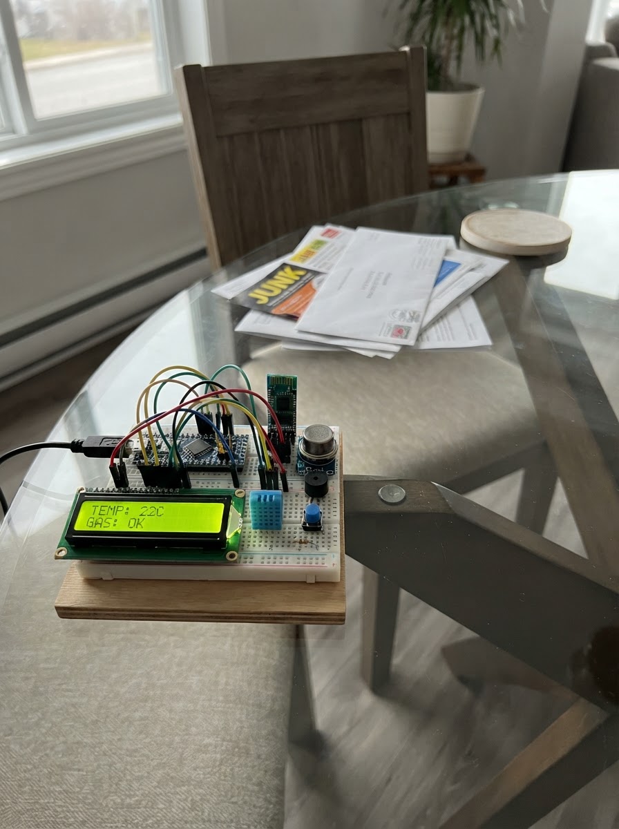
This project builds a wearable gas detection and environmental monitoring system using an ESP32 microcontroller. It combines temperature and humidity sensing with gas detection to create a personal safety device that alerts the wearer to hazardous conditions through both visual and audio feedback.
The guide provides a complete wiring diagram, parts list, and step-by-step assembly instructions for integrating the 16x2 LCD display, DHT11 climate sensor, MQ-2 gas sensor, piezo buzzer alarm, push button, and HC-05 Bluetooth module. The included firmware handles sensor reading, alarm triggering, display management, and wireless communication, allowing real-time monitoring and remote data access from a paired mobile device.
Wiring diagram

Gather all the parts
Assemble it in 5 steps
1. Place the controller and make power rails
Place the NodeMCU ESP8266 in the middle of the breadboard. Run one red wire from its 3V3 pin to a positive rail and one black wire from GND to a ground rail. Run a second red wire from VIN (5 V while USB powered) to a separate 5 V rail; do not join the 5 V and 3.3 V rails.
- Keeping 3.3 V and 5 V on different breadboard rails prevents accidental damage to the ESP8266 inputs.
- Do not connect the 5 V rail to any NodeMCU signal pin — ESP8266 pins can be damaged by 5 V.
2. Wire the LCD and climate sensor
Connect lcd_16x2 VCC to 3V3 (power), lcd_16x2 GND to GND (ground), lcd_16x2 SDA to NodeMCU D2 / GPIO4 (data), and lcd_16x2 SCL to NodeMCU D1 / GPIO5 (clock). Connect dht11_1 VCC to 3V3 (power), dht11_1 GND to GND (ground), and dht11_1 DATA to D3 / GPIO0 (signal).
- If the DHT11 is a bare four-pin sensor rather than a small three-pin module, add a 10 kΩ pull-up resistor from DATA to 3V3.
- The display may use address 0x27; if it stays blank after deployment, its board may instead use 0x3F.
- Make sure VCC and GND are not swapped on either module — swapped power can damage the parts.
3. Wire the alarm, button, and Bluetooth module
Connect piezo_1 Lead 1 to D5 / GPIO14 (alarm signal) and Lead 2 to GND (ground). Connect button_1 SIGNAL to D0 / GPIO16 (signal) and button_1 GND to GND (ground). Connect hc05_1 Vcc to VIN / 5 V (power), hc05_1 GND to GND (ground), hc05_1 TX to D6 / GPIO12 (Bluetooth data into the board), and hc05_1 RX to D7 / GPIO13 (Bluetooth data out of the board).
- The button uses the board's built-in pull-up, so it should read as a press only when it connects D0 to ground.
- Follow the labels printed on the HC-05 breakout board; TX and RX cross between the module and controller.
- Do not use an unregulated battery or supply on the HC-05 Vcc pin; use the board's USB-powered 5 V rail for this version.
4. Add the protected gas-sensor connection
Connect mq2_1 VCC to VIN / 5 V (heater power) and mq2_1 GND to GND (ground). Connect mq2_1 AO to one end of r_mq2_top. Join the other end of r_mq2_top to one end of r_mq2_bottom and to NodeMCU A0 (gas-level signal). Connect the remaining end of r_mq2_bottom to GND (ground). Use the two 10 kΩ resistors exactly as this divider.
- The joined resistor ends and A0 are one shared row on a breadboard.
- Let the MQ-2 warm up for several minutes before treating its reading as meaningful.
- Never connect MQ-2 AO straight to A0 — its 5 V output can damage the ESP8266 analog input.
5. Fit the electronics into the vest
After checking every wire, mount the board and modules inside a non-conductive pouch on the vest. Keep the MQ-2 sensor exposed to air and away from fabric, and route wires so they cannot pull loose when the wearer moves. Power the NodeMCU from USB for this design.
- Use strain relief such as tape or small cable ties near each module so a tug does not bend its pins.
- Place the buzzer opening and LCD where they can be heard and read.
- The MQ-2 heater gets warm during use; keep it away from skin, loose fabric, and anything flammable.
Review all connections
1. Connections between "lcd_16x2" and "ESP32"
2. Connections between "dht11_1" and "ESP32"
3. Connections between "piezo_1" and "ESP32"
4. Connections between "hc05_1" and "ESP32"
5. Connections between "mq2_1" and "ESP32"
6. Connections between "r_mq2_top" and "ESP32"
7. Connections between "r_mq2_bottom" and "ESP32"
8. Connections between "button_1" and "ESP32"
Deploy the firmware
#include <HardwareSerial.h>
#include <Arduino.h>
#include <Wire.h>
#include <LiquidCrystal_I2C.h>
#include <DHT.h>

// Forward declarations
String fit16(String text);
void showStatus(const String &line1, const String &line2);
bool readAcknowledgePress();

constexpr uint8_t LCD_SDA_PIN = 4;   // NodeMCU D2
constexpr uint8_t LCD_SCL_PIN = 5;   // NodeMCU D1
constexpr uint8_t DHT_PIN = 0;       // NodeMCU D3
constexpr uint8_t BUZZER_PIN = 14;   // NodeMCU D5
constexpr uint8_t BT_RX_PIN = 12;    // NodeMCU D6, receives HC-05 TX
constexpr uint8_t BT_TX_PIN = 13;    // NodeMCU D7, sends HC-05 RX
constexpr uint8_t MQ2_PIN = A0;
constexpr uint8_t BUTTON_PIN = 16;   // NodeMCU D0

constexpr int GAS_ALARM_LEVEL = 650;
constexpr unsigned long SAMPLE_INTERVAL_MS = 2000;
constexpr unsigned long DEBOUNCE_MS = 40;

LiquidCrystal_I2C lcd(0x27, 16, 2);
DHT dht(DHT_PIN, DHT11);
HardwareSerial bluetooth(2);

bool alarmAcknowledged = false;
bool previousButtonReading = HIGH;
bool stableButtonState = HIGH;
unsigned long lastButtonChangeMs = 0;
unsigned long lastSampleMs = 0;
String lastLine1;
String lastLine2;

String fit16(String text) {
  if (text.length() > 16) return text.substring(0, 16);
  while (text.length() < 16) text += ' ';
  return text;
}

void showStatus(const String &line1, const String &line2) {
  if (line1 != lastLine1) {
    lcd.setCursor(0, 0);
    lcd.print(fit16(line1));
    lastLine1 = line1;
  }
  if (line2 != lastLine2) {
    lcd.setCursor(0, 1);
    lcd.print(fit16(line2));
    lastLine2 = line2;
  }
}

bool readAcknowledgePress() {
  bool reading = digitalRead(BUTTON_PIN);
  if (reading != previousButtonReading) lastButtonChangeMs = millis();

  if ((millis() - lastButtonChangeMs) > DEBOUNCE_MS && reading != stableButtonState) {
    stableButtonState = reading;
    if (stableButtonState == LOW) {
      previousButtonReading = reading;
      return true;
    }
  }
  previousButtonReading = reading;
  return false;
}

void setup() {
  pinMode(BUZZER_PIN, OUTPUT);
  pinMode(BUTTON_PIN, INPUT_PULLUP);
  digitalWrite(BUZZER_PIN, LOW);

  Wire.begin(LCD_SDA_PIN, LCD_SCL_PIN);
  lcd.init();
  lcd.backlight();
  dht.begin();
  bluetooth.begin(9600, SERIAL_8N1, BT_RX_PIN, BT_TX_PIN);

  showStatus("Safety Vest", "Starting sensor");
  delay(1200);
}

void loop() {
  if (readAcknowledgePress()) {
    alarmAcknowledged = true;
  }

  if (millis() - lastSampleMs < SAMPLE_INTERVAL_MS) return;
  lastSampleMs = millis();

  float humidity = dht.readHumidity();
  float temperatureC = dht.readTemperature();
  int gasRaw = analogRead(MQ2_PIN);
  bool gasAlarm = gasRaw >= GAS_ALARM_LEVEL;
  bool dhtValid = !isnan(humidity) && !isnan(temperatureC);

  if (!gasAlarm) alarmAcknowledged = false;
  bool soundAlarm = gasAlarm && !alarmAcknowledged;
  digitalWrite(BUZZER_PIN, soundAlarm ? HIGH : LOW);

  String line1;
  if (dhtValid) {
    line1 = "T:" + String(temperatureC, 1) + "C H:" + String((int)humidity) + "%";
  } else {
    line1 = "DHT11 check";
  }

  String line2 = "Gas:" + String(gasRaw);
  if (gasAlarm) line2 += alarmAcknowledged ? " ACK" : " ALERT";
  showStatus(line1, line2);

  bluetooth.print("TEMP=");
  if (dhtValid) bluetooth.print(temperatureC, 1); else bluetooth.print("NA");
  bluetooth.print(",HUM=");
  if (dhtValid) bluetooth.print(humidity, 0); else bluetooth.print("NA");
  bluetooth.print(",MQ2=");
  bluetooth.print(gasRaw);
  bluetooth.print(",ALARM=");
  bluetooth.println(gasAlarm ? "1" : "0");
}
Remix this project
Make it yours in one click
Open a full copy of this project in your own Schematik workspace — diagram, code, parts, and assembly steps included. Swap the sensor, add features, or redesign the whole thing with AI. The author's original stays untouched.