Community project
Gimme Project Bellows Diagram Schematic Wiring E
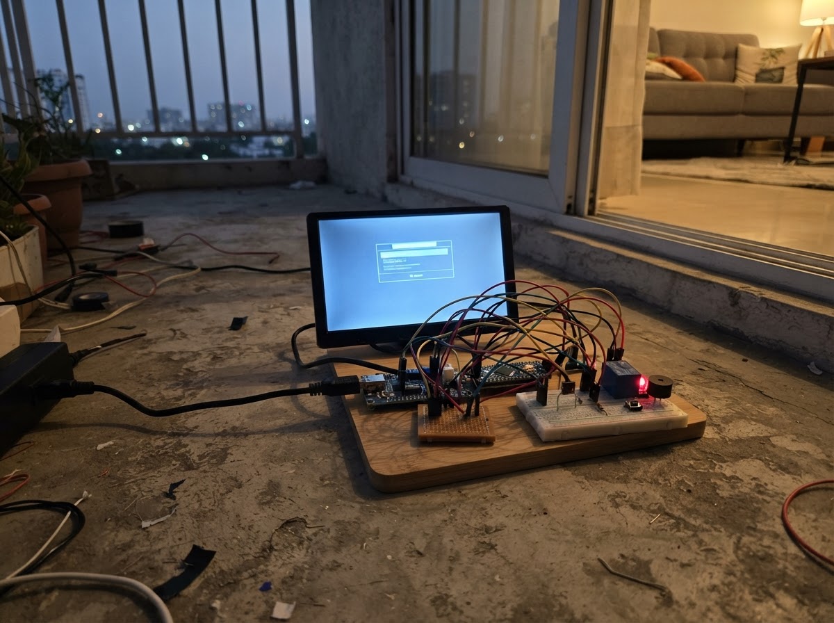
This project turns a 7-inch LCD monitor into a video display for a Commax DVP-4HP outdoor door panel, controlled by an Arduino Uno. The system uses a 12 V power supply, a buck converter to step down to 5 V for the microcontroller, and a relay module to switch the monitor on and off. A push button activates the display for 60 seconds, giving residents time to see who is at the door.
The guide includes a complete wiring diagram, parts list, and Arduino firmware with debounced button handling and automatic timeout logic. Assembly steps cover powering the outdoor panel, connecting the composite video feed, wiring the relay control, and integrating two push buttons. Note that door-release functionality is not verified in this version and remains disconnected.
Wiring diagram

Gather all the parts
Assemble it in 7 steps
1. Set the low-voltage supply
With the wall adapter unplugged, connect its positive output to the buck converter VIN+ and its negative output to VIN-. Use a multimeter to adjust VOUT+ and VOUT- to exactly 5.0 V before connecting the Uno or relay board.
- Make the 5-volt adjustment before attaching any 5-volt device.
- More than 5.0 V on the Uno 5V pin can damage the Uno and relay module.
2. Power the outdoor Commax panel
Connect adapter positive to the existing Commax terminal 3 yellow wire (power). Connect adapter negative to terminal 2 blue wire (ground). Leave terminal 1 red Voice disconnected in this video-only build.
- Label the four existing wires before tightening terminals.
- Do not connect the 12-volt adapter positive wire to terminal 2 or terminal 4; this can damage the outdoor panel or LCD.
3. Wire the LCD video lead
Connect Commax terminal 4 white wire directly to the RCA plug centre pin (video). Connect Commax terminal 2 blue wire directly to the RCA plug outer shield (ground). Do not fit the earlier 100 µF capacitor in this video lead.
- Keep the video cable away from relay and power wires to reduce picture noise.
- Never connect terminal 3, the 12-volt panel-power wire, to the RCA centre pin; it can damage the LCD video input.
4. Switch the LCD power
Connect adapter positive to the LCD relay COM terminal (power). Connect LCD relay NO to the LCD 12V+ lead (switched power). Connect LCD GND to adapter negative (ground). Leave the LCD relay NC terminal empty.
- NO means the screen is normally off and receives power only during the 60-second viewing period.
- Make sure the LCD positive and negative supply wires are not swapped — swapped power can damage the screen.
5. Wire the Uno and LCD relay
Connect buck VOUT+ to Uno 5V and LCD relay VCC (power). Connect buck VOUT- to Uno GND and LCD relay GND (ground). Connect LCD relay IN to Uno D7 (signal).
- Use one shared 5-volt rail and one shared ground rail for the Uno and LCD relay.
- Do not power the Uno through VIN from this regulated 5-volt output; use its 5V pin.
6. Add the two buttons
Connect one leg of the Monitor button to Uno D8 and its other leg to GND (signal and ground). Connect one leg of the Unlock button to Uno D6 and its other leg to GND (signal and ground). The current Unlock button safely turns on the screen only; it does not release the door.
- Place each button so its two used legs are on opposite sides of the breadboard centre gap.
- Do not connect either button to the Commax terminals; the Uno reads these buttons using its own 5-volt logic.
7. Leave unverified functions disconnected
Leave Commax terminal 1 Voice disconnected. Do not add a buzzer, PC817 detector, audio modules, 100 µF video capacitor, or door-release relay contacts. The original monitor schematic does not yet prove a safe replacement connection for those functions.
- Insulate every unused wire end separately with a terminal block or heat-shrink.
- Do not short any two Commax terminals to test door release; a wrong connection can damage the outdoor panel.
Review all connections
1. Connections between "power_adapter" and "Arduino"
2. Connections between "logic_buck" and "Arduino"
3. Connections between "lcd_relay" and "Arduino"
4. Connections between "lcd" and "Arduino"
5. Connections between "commax_outdoor" and "Arduino"
6. Connections between "monitor_button" and "Arduino"
7. Connections between "unlock_button" and "Arduino"
Deploy the firmware
#include <Arduino.h>

// Commax DVP-4HP documented four-wire connection:
// terminal 2 (blue) is common/video return, terminal 3 (yellow) is +12 V,
// and terminal 4 (white) is composite video. This project provides a manual
// 60-second LCD monitor function only. The door-release wiring is unverified.


// Forward declarations
void turnOnLcd();
bool buttonPressed(uint8_t pin, bool &lastReading, bool &stableState, unsigned long &changedAt);

const uint8_t LCD_RELAY_PIN = 7;
const uint8_t MONITOR_BUTTON_PIN = 8;
const uint8_t UNLOCK_BUTTON_PIN = 6;

const unsigned long LCD_TIMEOUT_MS = 60000UL;
const unsigned long DEBOUNCE_MS = 40UL;

bool lcdOn = false;
unsigned long lcdOffAt = 0;

bool lastMonitorReading = HIGH;
bool monitorStable = HIGH;
unsigned long monitorChangedAt = 0;

bool lastUnlockReading = HIGH;
bool unlockStable = HIGH;
unsigned long unlockChangedAt = 0;

void turnOnLcd() {
  lcdOn = true;
  lcdOffAt = millis() + LCD_TIMEOUT_MS;
  digitalWrite(LCD_RELAY_PIN, LOW);  // Active-low LCD relay: power on.
}

bool buttonPressed(uint8_t pin, bool &lastReading, bool &stableState,
                   unsigned long &changedAt) {
  const bool reading = digitalRead(pin);
  const unsigned long now = millis();

  if (reading != lastReading) {
    lastReading = reading;
    changedAt = now;
  }

  if ((now - changedAt >= DEBOUNCE_MS) && reading != stableState) {
    stableState = reading;
    return stableState == LOW;
  }
  return false;
}

void setup() {
  pinMode(MONITOR_BUTTON_PIN, INPUT_PULLUP);
  pinMode(UNLOCK_BUTTON_PIN, INPUT_PULLUP);
  pinMode(LCD_RELAY_PIN, OUTPUT);
  digitalWrite(LCD_RELAY_PIN, HIGH);  // Active-low LCD relay: power off.
}

void loop() {
  const unsigned long now = millis();

  if (buttonPressed(MONITOR_BUTTON_PIN, lastMonitorReading, monitorStable,
                    monitorChangedAt)) {
    turnOnLcd();
  }

  // The release path is not connected until the original Door-button circuit
  // is fully traced. For now, Unlock safely behaves like Monitor.
  if (buttonPressed(UNLOCK_BUTTON_PIN, lastUnlockReading, unlockStable,
                    unlockChangedAt)) {
    turnOnLcd();
  }

  if (lcdOn && (long)(now - lcdOffAt) >= 0) {
    lcdOn = false;
    digitalWrite(LCD_RELAY_PIN, HIGH);  // Active-low LCD relay: power off.
  }
}
Remix this project
Make it yours in one click
Open a full copy of this project in your own Schematik workspace — diagram, code, parts, and assembly steps included. Swap the sensor, add features, or redesign the whole thing with AI. The author's original stays untouched.
Related projects
I M Building Test-phase Prototype Of Capstone Co
Arduino · September 27, 2026Fritz Blue Gadaza
Ultrasonic Distance Alarm
Arduino · September 26, 2026Djimini3 Normal
Necesito Hacer Un Circuito De Un Oxiometro Con
Arduino · September 25, 2026MARIA PAULA LAMBOGLIA VARGAS