Community project
Handwired Macro Pad
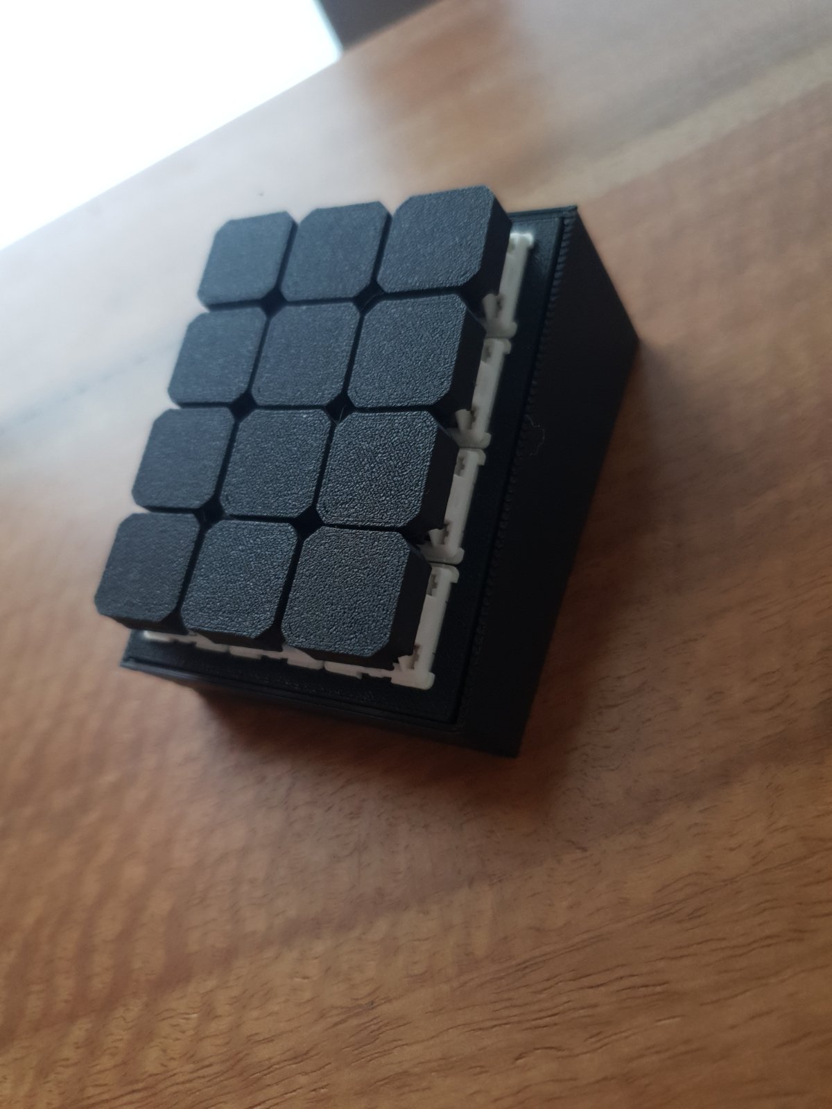
Build a 12-key macro pad from scratch using an Arduino Uno, push buttons, and signal diodes in a hand-wired matrix configuration. This guide covers the full assembly process: placing switches, soldering diodes to prevent ghosting, wiring rows and columns, and uploading firmware that scans the keyboard matrix and sends custom key codes to a connected computer.
The project teaches keyboard matrix scanning, debouncing techniques, and the Arduino Keyboard library. Builders will receive a complete wiring diagram, detailed assembly steps with diode polarity guidance, a full parts list, and customizable firmware that maps each of the 12 keys to any character or macro command.
Wiring diagram

Gather all the parts
Assemble it in 5 steps
1. Place the 12 switches
Press the 12 mechanical switches into the 3-by-4 plate so the two metal solder tabs of every switch are accessible from the back. Number the keys left to right: keys 1–4 on the top row, 5–8 in the middle, and 9–12 on the bottom.
- Use a marker or a small paper label to keep track of the rows before soldering.
- Do not heat a switch terminal for too long; excess heat can soften the plastic switch housing.
2. Make the three row wires
Solder one bare wire across one terminal of switches 1, 2, 3, and 4, then run that wire to Pro Micro D4 (row 1 signal). Repeat for switches 5–8 to D5 (row 2 signal), and switches 9–12 to D6 (row 3 signal).
- Keep each row wire separate and use three different wire colors if possible.
- The two switch terminals have no positive or negative side; simply use the same chosen terminal across each row.
- Make sure row wires do not touch each other — a solder bridge would make keys trigger incorrectly.
3. Solder one diode to every key
Solder the unstriped end of one 1N4148 diode to the unused terminal of each switch. The diode's painted stripe must face away from the switch; it will join a column wire next.
- The stripe is the line printed near one end of the tiny glass diode.
- Bend the diode legs first so they lie flat and do not press against nearby switch terminals.
- All 12 stripes must point away from their switches. A reversed diode makes that key fail or behave unpredictably.
4. Make the four column wires
Join the striped diode ends for keys 1, 5, and 9, then run that column wire to Pro Micro D7 (key signal). Join keys 2, 6, and 10 to D8 (key signal); keys 3, 7, and 11 to D9 (key signal); and keys 4, 8, and 12 to D10 (key signal).
- The four column wires run vertically through the key layout.
- Use heat-shrink tubing or electrical tape over exposed diode legs where they cross another wire.
- Do not connect a column wire to the row wire at any key; each key must connect through its own diode only.
5. Inspect before plugging in
With the Pro Micro unplugged, look closely for loose strands and solder blobs. Check that D4, D5, and D6 only go to row wires, while D7, D8, D9, and D10 only go to striped diode ends.
- A phone camera zoom can make it much easier to spot solder bridges.
- Use a multimeter continuity test if you have one: a key should connect its row to its column only while pressed.
- Do not plug in USB until you have checked for touching wires; a short can make the board hot or stop it working.
Review all connections
1. Connections between "switch_1" and "Arduino"
2. Connections between "diode_1" and "Arduino"
3. Connections between "switch_2" and "Arduino"
4. Connections between "switch_3" and "Arduino"
5. Connections between "switch_4" and "Arduino"
6. Connections between "switch_5" and "Arduino"
7. Connections between "switch_6" and "Arduino"
8. Connections between "switch_7" and "Arduino"
9. Connections between "switch_8" and "Arduino"
10. Connections between "switch_9" and "Arduino"
11. Connections between "switch_10" and "Arduino"
12. Connections between "switch_11" and "Arduino"
13. Connections between "switch_12" and "Arduino"
14. Connections between "diode_2" and "Arduino"
15. Connections between "diode_3" and "Arduino"
16. Connections between "diode_4" and "Arduino"
17. Connections between "diode_5" and "Arduino"
18. Connections between "diode_6" and "Arduino"
19. Connections between "diode_7" and "Arduino"
20. Connections between "diode_8" and "Arduino"
21. Connections between "diode_9" and "Arduino"
22. Connections between "diode_10" and "Arduino"
23. Connections between "diode_11" and "Arduino"
24. Connections between "diode_12" and "Arduino"
Deploy the firmware
#include <Arduino.h>
#include <Keyboard.h>

// Hand-wired 3 x 4 keyboard matrix.
// Diode direction is COL2ROW: switch -> diode anode, diode stripe/cathode -> column.
const uint8_t ROW_1_PIN = 4;
const uint8_t ROW_2_PIN = 5;
const uint8_t ROW_3_PIN = 6;
const uint8_t COL_1_PIN = 7;
const uint8_t COL_2_PIN = 8;
const uint8_t COL_3_PIN = 9;
const uint8_t COL_4_PIN = 10;

const uint8_t rowPins[3] = {ROW_1_PIN, ROW_2_PIN, ROW_3_PIN};
const uint8_t colPins[4] = {COL_1_PIN, COL_2_PIN, COL_3_PIN, COL_4_PIN};

// Change these entries later to choose what each physical key sends.
const char macroKeys[3][4] = {
  {'1', '2', '3', '4'},
  {'5', '6', '7', '8'},
  {'9', '0', '-', '='}
};

bool previousPressed[3][4] = {};
unsigned long lastChangeMs[3][4] = {};
const unsigned long DEBOUNCE_MS = 20;

void setup() {
  // Rows normally listen with pull-up resistors enabled.
  for (uint8_t row = 0; row < 3; row++) {
    pinMode(rowPins[row], INPUT_PULLUP);
  }

  // Columns are released except for the one currently scanned.
  for (uint8_t col = 0; col < 4; col++) {
    pinMode(colPins[col], INPUT);
  }

  Keyboard.begin();
}

void loop() {
  const unsigned long now = millis();

  // This is the same COL2ROW scan direction used by the QMK config discussed.
  for (uint8_t col = 0; col < 4; col++) {
    pinMode(colPins[col], OUTPUT);
    digitalWrite(colPins[col], LOW);
    delayMicroseconds(30);

    for (uint8_t row = 0; row < 3; row++) {
      const bool pressed = (digitalRead(rowPins[row]) == LOW);

      if (pressed != previousPressed[row][col] &&
          now - lastChangeMs[row][col] >= DEBOUNCE_MS) {
        previousPressed[row][col] = pressed;
        lastChangeMs[row][col] = now;

        if (pressed) {
          Keyboard.press(macroKeys[row][col]);
        } else {
          Keyboard.release(macroKeys[row][col]);
        }
      }
    }

    pinMode(colPins[col], INPUT);
  }
}
Download project files
Remix this project
Make it yours in one click
Open a full copy of this project in your own Schematik workspace — diagram, code, parts, and assembly steps included. Swap the sensor, add features, or redesign the whole thing with AI. The author's original stays untouched.
Related projects
Necesito Hacer Un Circuito De Un Oxiometro Con
Arduino · September 25, 2026MARIA PAULA LAMBOGLIA VARGAS
Laser Harp Instrument
Arduino · September 25, 2026juliasualoka2
Três Sensores de Luz
Arduino · September 25, 2026arthur.brazil