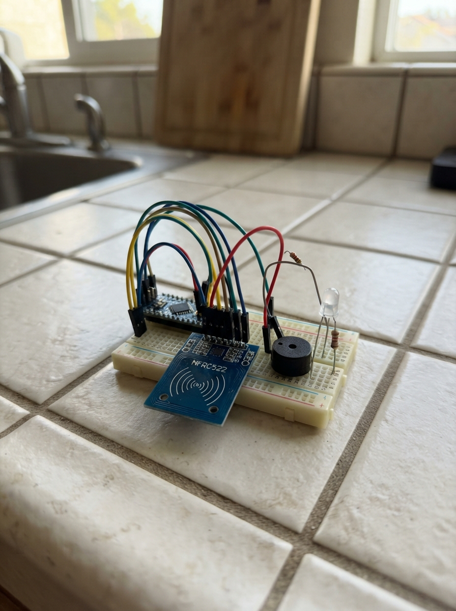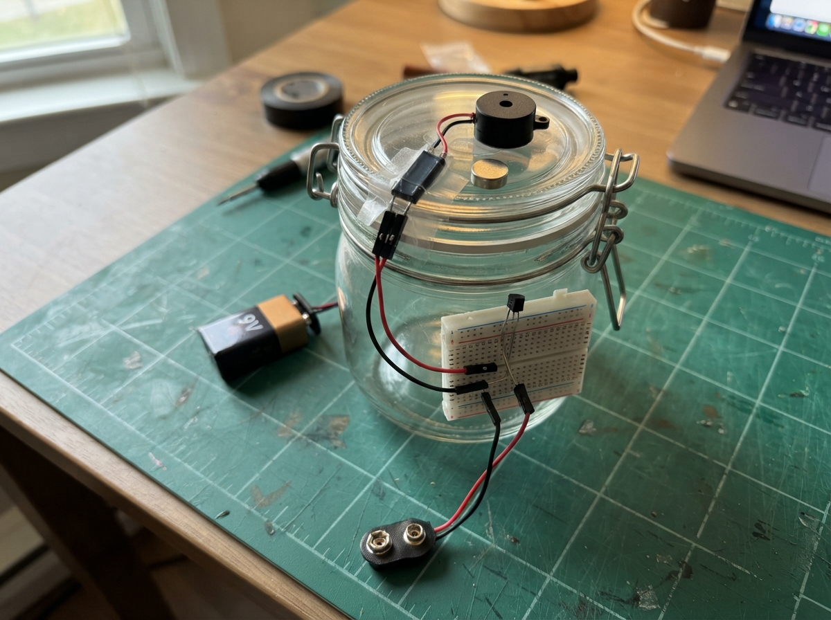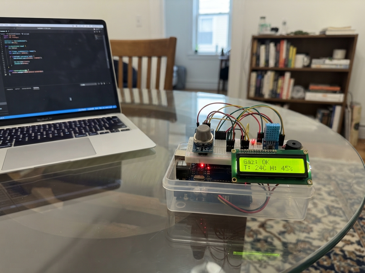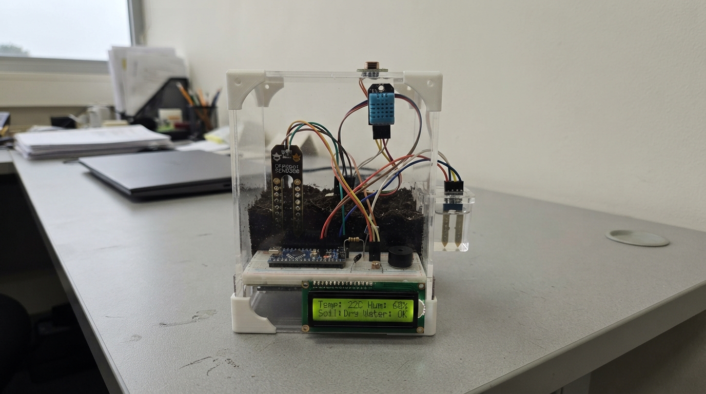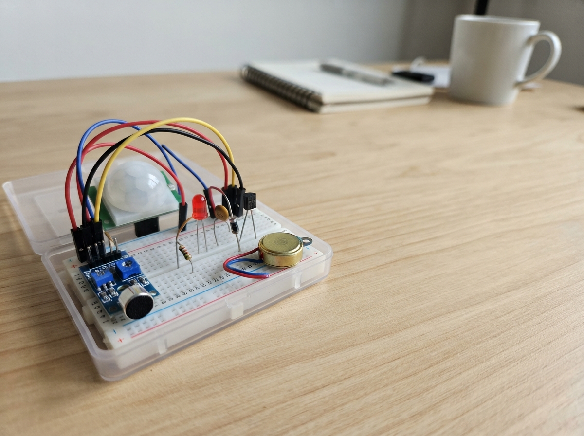
This household alert system combines sound and motion detection to trigger visual and tactile warnings. Built around an Arduino Uno, it uses a KY-038 sound sensor and HC-SR501 PIR motion sensor to monitor for activity, with LED indicators and a vibration motor providing immediate feedback when alerts are triggered.
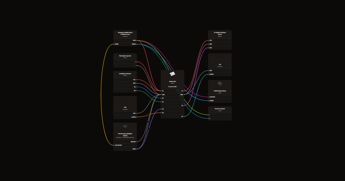
The guide includes a complete wiring diagram showing how to connect both sensors to the Arduino's digital inputs, wire the LEDs through current-limiting resistors, and build a transistor-based motor driver circuit with flyback protection. Assembly steps cover power rail preparation, sensor calibration, indicator light configuration, and motor driver construction, along with the firmware needed to detect sound and motion events with adjustable alert timing.
Wiring diagram
Gather all the parts
Assemble it in 6 steps
1. Prepare the power rails
With USB unplugged, connect UNO 5V to the breadboard positive rail and GND to the negative rail. Bridge split rails if your breadboard has them. Use USB power only for this prototype.
2. Connect the sensors
Connect KY-038 VCC to 5V, GND to ground, AO to A0 (raw sound reading), and DO to D2 (threshold trigger). Connect HC-SR501 VCC to 5V, GND to ground, and OUT to D3 (motion signal). Follow the printed pin labels, not guessed pin order.
- Leave A4 and A5 unconnected for a future OLED.
- Allow 60 seconds for the PIR to settle. Set its time control near minimum for testing.
3. Connect the two indicator lights
Connect D8 through its 220 ohm resistor to the red LED long leg. Connect D9 through its separate 220 ohm resistor to the blue LED long leg. Both short legs go to ground.
4. Build the motor switch
Use a P2N2222A transistor. Connect D6 through 1 kiloohm to its base, emitter to ground, and collector to motor negative. Connect the 10 kiloohm resistor between base and ground to keep the motor off at startup. Connect the specified 5V FM0610-032 motor positive to 5V.
- Verify emitter/base/collector against the exact transistor supplier pinout before powering. Similar transistor names may have different leg orders.
- Do not substitute a 3V coin motor on the 5V rail. Keep the rotating weight unobstructed and away from fingers.
5. Protect and steady the motor supply
Connect the diode across the motor, striped cathode to motor positive and anode to motor negative. Connect the 100 nF ceramic capacitor across the same motor terminals. Place the 100 microfarad capacitor across 5V and ground near the driver, positive lead to 5V and marked negative lead to ground.
- A reversed diode can short the supply when the motor switches on. A reversed electrolytic capacitor can rupture.
6. Position and calibrate the prototype
Secure the motor housing to a surface the person can touch, leaving its moving weight free. Separate the microphone from the motor to reduce self-triggering. Aim the PIR into the monitored area. Keep the room quiet during the first two seconds after powering, then adjust the KY-038 trimmer until the desired test sound changes its trigger indicator. Restart quietly after adjustment.
- Test sound alone, motion alone, and both together. Sound gives red flashes and long vibrations; motion gives blue flashes and paired short vibrations.
- When both alerts overlap, motor pulses combine; use the two LEDs to identify the triggered sensors.
- If the motor causes sound alerts, increase physical separation and adjust the sound threshold, then retest with the motor running.
- Plug in USB and press Deploy in Schematik. No simulation setting or extra library is needed.
- Both LEDs flash once per second. Alerts last four seconds.
- This is a demonstration prototype, not a certified fire, security, or emergency alert system.
- It detects sound thresholds, not particular alarm types or calibrated decibel levels. Vibration is only useful with physical contact.
- Motor startup and stall current are not specified in the available motor table. Do not obstruct the rotating weight; disconnect power if the motor stalls or the board resets.
Review all connections
1. Connections between "sound" and "Arduino"
2. Connections between "motion" and "Arduino"
3. Connections between "red_resistor" and "Arduino"
4. Connections between "red" and "Arduino"
5. Connections between "blue_resistor" and "Arduino"
6. Connections between "blue" and "Arduino"
7. Connections between "base_resistor" and "Arduino"
8. Connections between "pulldown" and "Arduino"
9. Connections between "transistor" and "Arduino"
10. Connections between "motor" and "Arduino"
11. Connections between "diode" and "Arduino"
12. Connections between "decoupling" and "Arduino"
13. Connections between "bulk" and "Arduino"
Deploy the firmware
#include <Arduino.h>
// No simulated inputs: real KY-038 DO triggers; AO is diagnostic only.
constexpr uint8_t SOUND=2, PIR=3, MOTOR=6, RED=8, BLUE=9;
constexpr unsigned long WARMUP=60000, ALERT=4000;
bool idleSound=HIGH, lastSound=false, lastMotion=false;
bool soundAlert=false, motionAlert=false;
unsigned long soundStart=0, motionStart=0, lastReport=0;
uint16_t highVotes=0, samples=0;
unsigned long bootTime=0, lastCalibrationSample=0;
bool pirReady=false;
void setup() {
  digitalWrite(MOTOR,LOW); pinMode(MOTOR,OUTPUT);
  pinMode(RED,OUTPUT); pinMode(BLUE,OUTPUT);
  pinMode(SOUND,INPUT_PULLUP); pinMode(PIR,INPUT);
  bootTime=millis();
  Serial.begin(115200);
  Serial.println(F("Keep quiet for first 2 seconds: learning sound idle level. PIR warms up for 60 seconds."));
}
void loop() {
  unsigned long now=millis();
  unsigned long sinceBoot=now-bootTime;
  if(sinceBoot<2000) {
    // Sample once per millisecond: counters cannot overflow during calibration.
    if(samples==0 || now-lastCalibrationSample>=1) {
      lastCalibrationSample=now;
      highVotes += digitalRead(SOUND)==HIGH;
      ++samples;
    }
    return;
  }
  // Latch readiness so the millis rollover does not restart warm-up.
  if(!pirReady && sinceBoot>=WARMUP) pirReady=true;
  static bool calibrated=false;
  if(!calibrated) {
    idleSound=highVotes>samples/2;
    calibrated=true;
    Serial.print(F("Sound idle level: ")); Serial.println(idleSound);
  }
  bool sound=digitalRead(SOUND)!=idleSound;
  bool motion=pirReady && digitalRead(PIR)==HIGH;
  // Rising edges start finite alerts; a held sensor does not run the motor forever.
  if(sound && !lastSound && !soundAlert) {
    soundStart=now; soundAlert=true; Serial.println(F("Sound alert"));
  }
  if(motion && !lastMotion && !motionAlert) {
    motionStart=now; motionAlert=true; Serial.println(F("Motion alert"));
  }
  lastSound=sound; lastMotion=motion;
  if(soundAlert && now-soundStart>=ALERT) soundAlert=false;
  if(motionAlert && now-motionStart>=ALERT) motionAlert=false;
  // LEDs: one flash per second, independent for simultaneous events.
  digitalWrite(RED,soundAlert && (now-soundStart)%1000<500);
  digitalWrite(BLUE,motionAlert && (now-motionStart)%1000<500);
  // Sound: one long vibration. Motion: two shorter vibrations each 2-second cycle.
  unsigned long s=(now-soundStart)%2000, m=(now-motionStart)%2000;
  bool vibration=(soundAlert && s<800) || (motionAlert && (m<250 || (m>=500 && m<750)));
  digitalWrite(MOTOR,vibration);
  if(now-lastReport>=1000) {
    lastReport=now;
    Serial.print(F("AO(raw, not dB)=")); Serial.print(analogRead(A0));
    Serial.print(F(" DO=")); Serial.print(digitalRead(SOUND));
    Serial.print(F(" PIR=")); Serial.print(digitalRead(PIR));
    if(!pirReady) Serial.print(F(" warming up"));
    Serial.println();
  }
}
Remix this project
Make it yours in one click
Open a full copy of this project in your own Schematik workspace, diagram, code, parts, and assembly steps included. Swap the sensor, add features, or redesign the whole thing with AI. The author's original stays untouched.